Picked up my Nevada yesterday and noticed the aerial wasn’t working, had a good root and it had been unplugged, plugged it back in and hey presto it worked … For about an hour! Came back out to the car to hear the motor clicking away like mad, put the keys in and turned the radio on and it came up about a foot before it stopped, took it all apart cleaned it and put it back in and it worked again but guess what a short time later with the aerial fully down and no keys in the car, click click click again so I’ve done what the last owner did and unplugged it, so any ideas anyone? Maybe some damaged teeth further up the mast? Or circuitry issue? But why the clicking with no keys or ignition??? This is the first and most annoying gremlin I need to fix!!
Hi
If the mast is intermittently able to work, it sounds like the usual suspect, broken/bent mast or nylon cable broken out of top mast section is not the issue. My best guess is that the primary plastic cog that runs off the metal screw on the motor has worn away to some extent. This means the motor will work but not engage completely.
In early days of refurbishing these I had a spare and sold it. Now have at least 2 aerials that are waiting for one of these.
Take it apart again and look at that white cog. When the white plastic cover is out of the way it can be carefully lifted out with a pair of screwdrivers. You will see the thread worn in a dish shape if it has been over stressed. I don’t think spares are available so you will need to source a replacement aerial.
Thanks for the quick response, I will take it apart in the morning and take a look will try and put some pics up as well, when I looked at it first thing I noticed was the chord was sticking out of the big wheel which I assume is there to keep it wrapped up neatly, that wheel was not attached to the main shaft that it sits on is that correct, under that I exposed the white flat plastic part which then sits over the main gear wheel could the nylon be getting stuck somewhere between any of these things?
If you took the aerial apart with the mast down, most of the cable will be wrapped under pressure in the domed wheel. The cable should feed through the slot in the base plate and then into the domed wheel which rotates to facilitate storage. Much easier to put it all back together with the aerial almost fully extended to minimise the pressure exerted by a shorter length of wrapped cable. The domed wheel should contain all spare cable but as you say sits freely on the centre hub. You need to make sure it stays down containing all the spare cable when you put the main body back together.
It all gets a lot easier when you have stripped 50 or so of these:-)
Normal mode is the power is on directly to the DOWN mode, so when you turn the ignition or the radio off, the aerial will retract automatically. While the clicking sound you hear could be down to the worn gear or a loose cable, it could also be the retract limit switch is faulty. Try and fix the cable and nylon cog first, then see if the problem still occurs.
Might be easier to get a S/H hand unit complete?
Was thinking about replacing the lot until I saw the cost! I have seen some universal ones for around £25 that should work if I just splice the cables from the new one into the old loom, has anyone else used one of these
right i think i have the problem, it seems to be the white cog by the motor, i had it plugged in with just the base plate over it and the clicking seemed to be coming from that area so im guessing that the teeth are just worn enough to skip over the screw thread on the motor, is there any way of fixing this as i cant afford £60+ for a complete new unit

Just a thought … might be worth trying.
I know that a similar type motor and worm gears are used to provide tilting of electric door mirrors.
A friend on the Lexus forum had a similar issue to what you have described. He cleaned all the cogs and worm drives thoroughly (with an old toothbrush and some solvent) to get all the old grease and accumulated crud out, and then just applied a sparse amount of grease to assist the movements … bingo … it fixed the problem.
Its worth trying as you have got the lot exposed.
Hope it works for you.
No Mike, unless you are the clever person who can find a source of these cogs new. I have put a lot of time into this and now have three aerials that require this cog.
If you refer to my previous posts you will see that this was clearly explained…or at least I thought it was clearly explained?
That leaves you with the best option of buying one of my £60+ aerials - refurbished,cleaned and guaranteed.
P.S. if you can find a cheap source of the primary plastic cogs I will post you out one of my aerials for nothing - I think you can afford that:-)
Have you tried HPC Gears? I used them a lot when I was still working.
WE have good used electric aerials if your still looking
Thanks Richard - this cannot be too costly an exercise but worth a few quid to save an aerial or three.
Perhaps a 3D printer could replicate.
for interest please see photo of damaged cog with dish shaped wear.
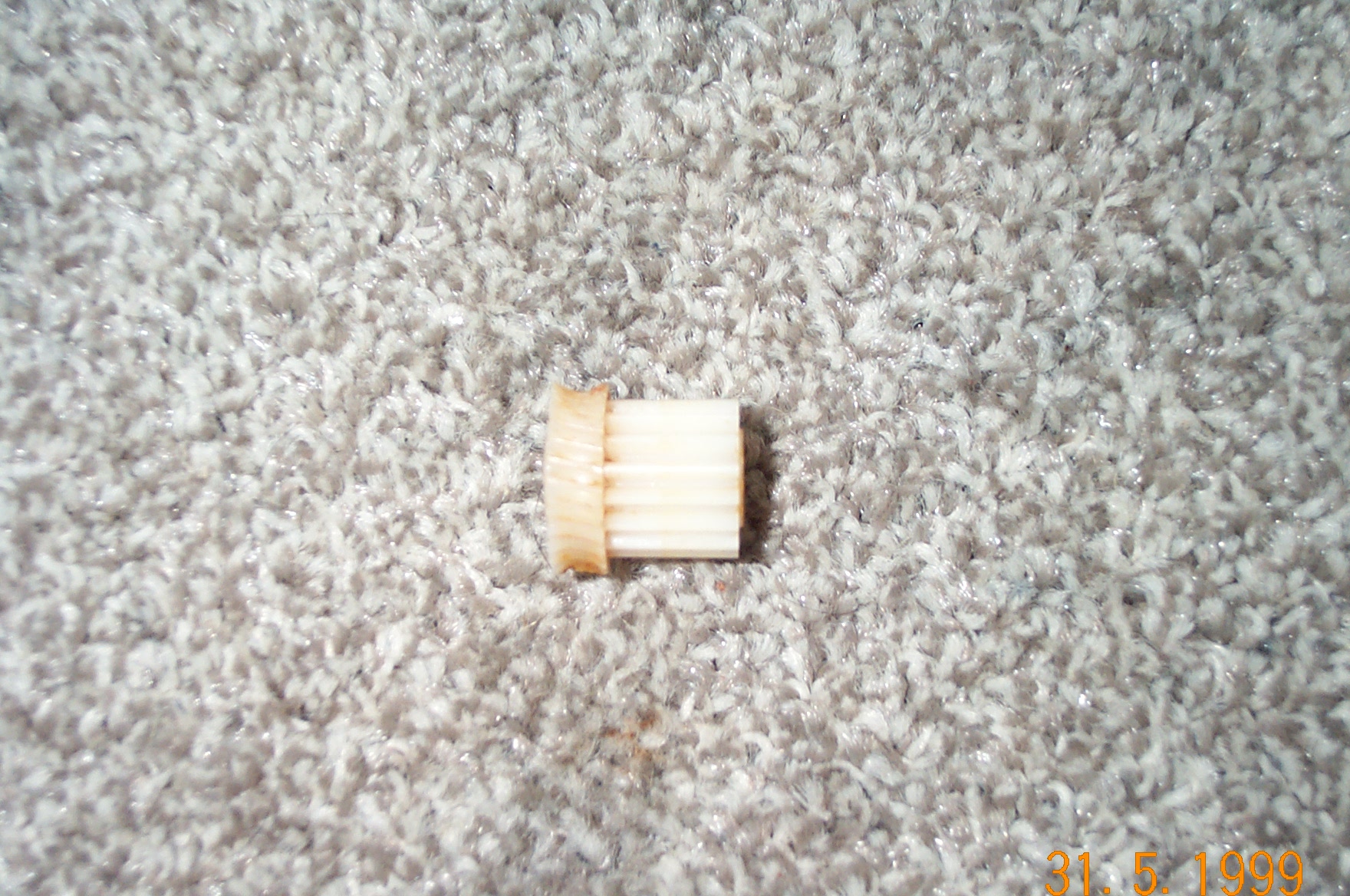
Ah, that is not just a simple Wheel gear for the Worm drive, it also has a Spur gear as the other part of it. That complicates matters, because it is obviously a one-piece cast compound gear.
The 3D printing sounds much more like a goer, because the gear shapes are mathematically defined so the part could be simply described by some clever formulae. I have no idea about the costs, or if the printer can print Delrin. Alas, my maths is no longer up to specifying the gear shape. I guess the easy way is to 3D scan a good one and print a copy.
However, if you want to be really bored to tears then read on…
The Worm and Wheel cat in HPC always shows the wheel gear with the dishing to mate with the shape of the worm gear for maximum contact length along each tooth.
Going by the photo of the motor/gearbox assembly you have a 1 start Worm and a 27 tooth Wheel. Which makes life awkward because their standard sizes don’t include the 27 tooth variety. Also to keep costs within reason you would need to machine off the damaged portion and pin the new Wheel to the remaining bit of spur gear. That would be a royal pain, and probably impractical.
There is a convention for gears where the pitch of the teeth and the number of teeth defines the Module or Modulus, mainly because it is so difficult to measure the actual gear diameter at the contact point (PCD). The HPC cat lists the following parts
Mod of 0.4 with 26 teeth gives a possible PCD of 10.4mm, or 11.6mm across tips on a 4mm thick wheel
Mod of 0.4 with 28 teeth gives a possible PCD of 11.2mm, or 12.4mm across tips on a 4mm thick wheel
Mod of 0.5 with 25 teeth gives a possible PCD of 12.5mm, or 14mm across tips on a 5mm thick wheel
Mod of 0.5 with 28 teeth gives a possible PCD of 14mm, or 15.5mm across tips on a 5mm thick wheel
Extrapolating for Mod 0.5 and 27 teeth then PCD would be 13.5mm and 14.9 across tips.
This is all a bit academic really. I don’t see HPC as being economic with that compound gear.
Thanks again Richard. Not an engineer myself but parallel mentality as worked as a computer programmer for years.
Lots of interest with engineering but requiring the relevant theory explained to back it up.
You are right about the cog - it is 27 teeth above the spur of 16 teeth. I imagine it is delrin. I know nothing about 3d printing but believe it may be possible to use delrin although acetal(pom) is the standard material.
The actual cog as photographed may well be a three piece item - I am thinking a tube with the two cogs fitted to it. My problem is poor close up eyesight and no natural light today to check for joins.
A proper design would indeed be a dished out cog to distribute the stress of mating with the motor worm equally. The fact they have used a flat profile would significantly reduce the amount of pressure required to strip the cog and hence the problem. At a guess the contact surface area would be increased by 100% if the correct design was in place.
I like the idea of using a 3D printer. I’ll ask a friend of mine who has one. I have an old cog with this problem I can give him to see what he thinks.
AFAIK - 3D printers can use nylon - that’s tough enough surely?
Funnily enough, I’ve been considering it for a while, but not up to programming stuff, or 3D CAD either - it’s 4X more than a printer. There’s loads of work available, for broken replacements, but broken can mean bits missing, so you can’t always produce an exact replacement.