There’s a post on the forums from a forum technical on how to fit after market central locking, and although it gave me the confidence to try it myself, I thought I’d write a (only slightly) more detailed one to let people know the tricks I used to make the task simpler.
The kit
First off, the kit I’m using was £35 on ebay:
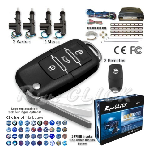
I chose this one as it had several plus points:
- Has 2 masters which can activate the other locks when used (some kits only have 1 master).
- Has the ability to interface with a boot popper and total closure (windows close too when you lock the car).
- Has nice flip out key fobs and allows you to choose Mazda logo on fob and comes with correct Mazda key blanks to get cut, and also comes with black on black printed buttons as well as the white ones.
The unit is mounted in the boot in the cavity behind the driver’s seat rather than up front which is where I’m guessing most people would fit it. I chose the boot as I’ve fitted a second fusebox in there already to cope with all the gadgets I have and will be installing, and it provides easy access if I ever need to get to the unit. The only issue this caused is that the wiring loom for the kit I purchased was not long enough to reach the passenger door so I needed to splice in an extra metre or two to each wire to allow it to reach comfortably. Running the loom out for a length check before starting the job would be recommended.
Note on wiring & soldering
I soldered wiring connections whenever possible, and used proper spade terminals to connect components. This makes for much better connections that won’t unwind or come apart when pulled. I also used heat-shrink tube where possible, otherwise insulation tape to insulate connections. Maplins sells all of this quite cheaply.
Running cables to the doors
Running the cables behind the seats and along the sides to the doors is quite easy, but the trouble comes when trying to run them through the bulkheads and connectors between the cockpit and the doors. My first tip is that I used a spare length of stiff (stiff I emphasise) co-ax cable to pull through the wires whenever necessary. This made the job an absolute breeze and I’d probably still be trying (and failing) if I hadn’t done this… It solved all my problems! You need to use stiff co-ax with a solid plastic core which is stiff enough to force it’s way through the joints but flexible enough to bend around bulkheads.
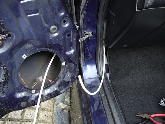
(image shows co-ax cable pushed all the way through before taping wires to the end and pulling through)
Then, just duct tape the wires to the end of the length of co-ax that you’ve already poked through the hole and then pull the whole lot through together (making the taped connection as streamlined as possible to avoid snagging)! I also used a Stanley knife to trim some of the inner workings of the rubber joint away which was causing me trouble. I found the best way was to seperate the flexible rubber joint from the car’s body and then poke the length of co-ax from inside the door through the rubber joint, then through the plastic grommet, then through the hole in the body panel and fish around for it under the dashboard when it finally came through.
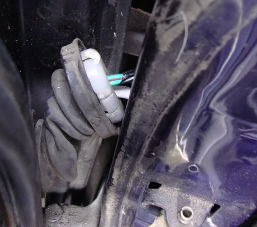
If you compare the image above to what you see if you pull the connector from the door, you’ll see I’ve cut out a piece of rubber from the middle of the plastic piece which was making things impossible. You can also see the white co-ax cable I fed through before using it to pull the softer cables through.
After getting the co-ax through, it was a simple process to tape the locking wiring to the end and pull it all back together.
Fitting the door actuators
The actuator was installed in the door as follows using the provided mounting strips, but using galvanised nuts and bolts instead of the self tapping screws provided with the kit. Rivets would have also worked well.
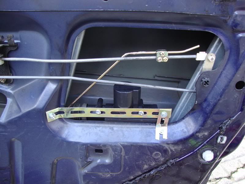
Of course you have to ensure that it doesn’t foul the window mechanism but I found this was the best place for it.
And that was it for the central locking! I mentioned that this unit has the ability to pop the boot, and a button on the keyfob just for that so I thought it would be a shame not to put it to use, plus I ordered the kit with 4 actuators knowing that two would be spare and I could use one for the boot…
Boot popping
The boot opener output from the locking unit does not provide enough power to activate an actuator, so for this I needed a pre-empted visit to Maplin to get an automotive relay (30A, 12V automotive relay for about £2). Fitting the actuator to the boot catch was again a simple task and I was only slowed down by my inability to attach wires where I know they should be going! You should (or at least I should have) plan your circuit first on paper and preferably colour code your wires so a final check is made much simpler and errors can be caught quickly.
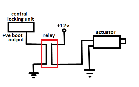
Image below shows the boot popper fitted: (note I have actually only used duct tape to hold the actuator in place as there was a cable taped there that I tried to move, but as it was duct taped down and impossible to budge, I thought I’d try duct tape for the brackets too! I’ll probably drill through and fit galvanised bolts here at some point though, or rivets if it’s tricky to get at the other side of the bulkhead.
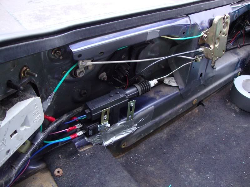
(Photo taken from across rear wing looking backwards in to the boot. Note the automotive relay neatly cable-tied to one of the actuator’s brackets)
When I have time, I’ll heat shrink all the relay’s connections to protect against water, not that there should be a lot of water getting in there…
Flashing indicators
Next step was to make the indicators flash when the unit was activated (lock, lock-check, unlock, boot pop). The central locking unit has a positive feed for the indicators but the instructions didn’t state the power capabilities, and I wasn’t sure how much current flashing all indicators on the car would draw. Also, I’d read that making indicators flash invariably requires diodes etc. to stop all indicators being connected together as one circuit and looking at the lighting circuit diagram in the back of the Haynes guide, it looked like I would have to make four connections minimum (and then what about the repeaters?). I decided to go for a much easier option! I used the positive output from the unit to activate another 30A 12V relay from Maplins, and used the second circuit in the relay to ground the hazard warning switch circuit (when you press the hazard warning light switch, it connects a ground circuit). All this required was a relay attached to the side of the central locking unit (using black tape, who cares as it’s hidden away anyway?) and then running a single wire to the dashboard and connecting it to the non-grounded wire on the hazard warning switch. For a good connection, I carefully sliced off the insulation from 5mm of the wire to the switch and spliced & soldered the additional line to it before insulating with tape. If you haven’t got a soldering iron, a splice connector may work (Maplins or Halfords), or just doing the same without soldering but winding and taping the connection firmly. It would be a bit of a bodge but if you’re happy with it, and bear in mind it could come apart later then it’s up to you…
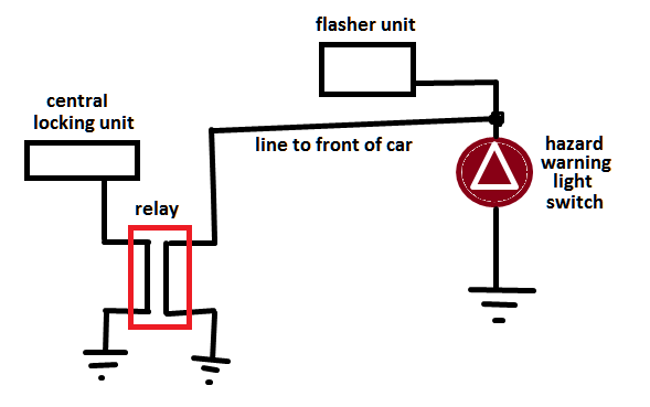
It’s a bit of a hack but only took a few minutes to wire up (easier as I was fitting the stereo at the same time so already had the centre console off, but would have been well worth the extra ten minutes to remove the console if I hadn’t). If anyone has a better/simpler suggestion on how to wire up the indicators to flash, please comment!
Completed!
And voila! A central locking kit with boot popper and flashing indicators fitted by a complete amateur in only a few hours!
If anyone has questions, please let me know. I was quite hesitant about attempting this task by myself with minimal experience, but having completed it I can say that with the correct tools, patience, thought and persistance, it can be done!
 .
.


