My experience with the CTEK is with the negative connected to chassis (not directly to the battery negative) so in line with the recommendation. Not sure if it’s a CTEK specific issue.
FWIW my Audi has no issue with the CTEK, also connected negative-to-chassis. The A3 actually has a ‘tab’ to connect the negative from chargers (which is on the firewall/chassis) so and they don’t recommend you attach anywhere else (like the battery terminal, hence avoiding the sensor)
Fair enough, but compared with the number of cars produced the odd grenading gearbox might just be early life failures that happens with any component. And you do get genuinely useful features in later cars, like adaptive headlights (the segmented ones that stay on high beam and dynamically turn off sections so as not to blind oncoming or followed cars). That feature has transformed nightime driving for me
Using a remote earthing point would include the current sensor, wouldn’t it?
I suspect this is not always to do with the battery monitoring anyway. Generic instructions for years have said when using jump leads or battery charging to connect the positive lead first the negative lead should be attached to the chassis, remote from the battery.. Sometimes they add “to prevent risk of explosion” or similar, presumably to avoid arcing at the battery.
I tend not to bother with this for charging, I connect it up first then switch the charger on.
Wouldn’t the battery monitor be less confused if it was allowed to measure the charge current?
Cars used to be simple. Now even the technicians don’t know what they are doing, they just follow prescribed algorithms.
Maybe the current sensor on Audis is in a different location compared to Mazda, or it’s smart enough to know that with the car parked that it’s a reverse charging current into the battery while it’s charging from a CTEK so it can ignore this as a potential drain issue like the Mazda seems to think if connected with the sensor in the charge path?
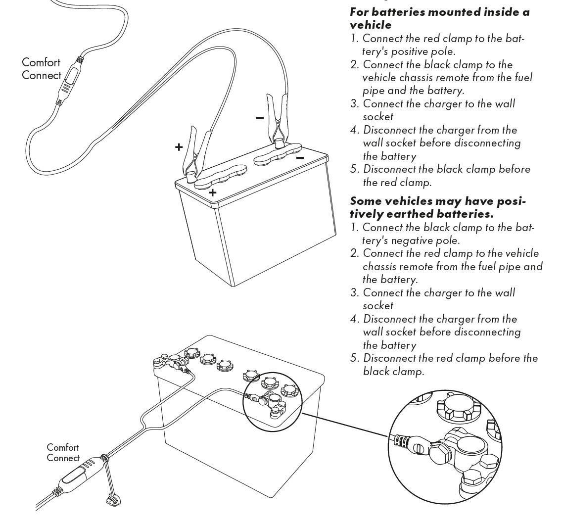
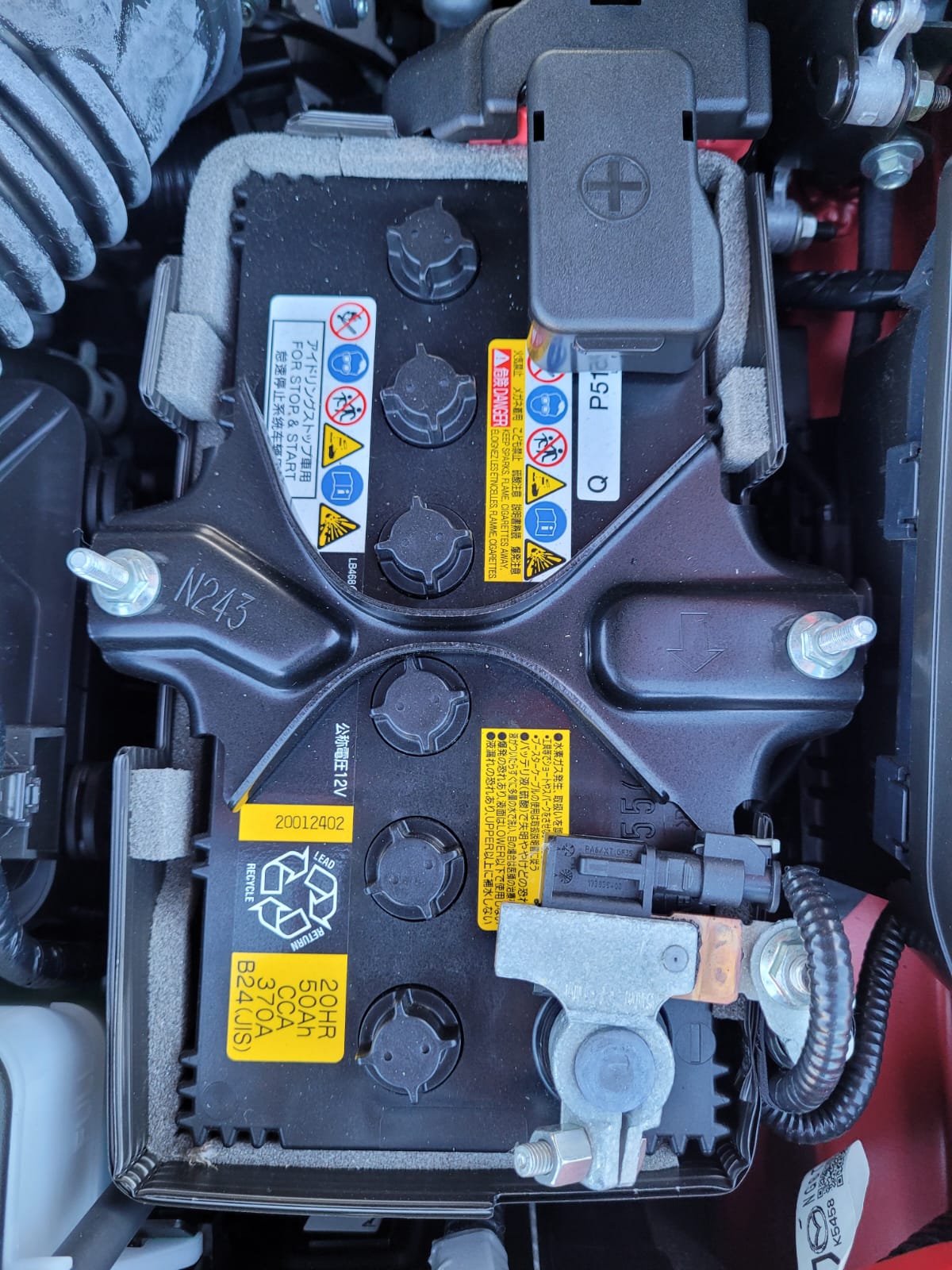
BTW, The CTEK MXS 3.8 PDF manual clearly shows to connect their charger directly to the battery posts thereby eliminating the current sensor module. So I’ll be using the lowest shown nut and bolt connection directly under the negative battery post in my MX-5 RF…
On my ND2 R-Sport 1.5, with stop-start, I’ve been using the CTEK MX5 5.0 charger on normal setting and connecting the negative lead to the chassis, I also do the same on my Ford Focus Mk4 which also has stop-start. I am able to fully charge the battery on both with no issues.
At the end of the day, if the battery is remaining connected to the car whilst charging, the current should flow through (and not avoid) the sensor so the Battery Management System knows what energy is being put back into the battery and it knows its SOC.
If you don’t do this the car’s BMS doesn’t know the battery has been charged and thinks it’s still in a lower state of charge. This is why you should connect via the chassis.
However the MX5 (with i-stop) experience at least for some is that even connected to the chassis the BMS doesn’t register the charging current so still thinks the battery is low. Disconnecting/reconnecting the battery seems to force the BMS to ‘re-evaluate’ what’s been connected, I guess because it assumes it might be an altogether different/new battery.
It might be that only the CTEK charges in a way that confuses the BMS in the MX5?
Maybe that’s the issue, the Mazda’s current sensor has no way of knowing which way that relatively small current is flowing, either into the battery or out of the battery so potentially a high parasitc drain is wrongly diagnosed while parked and being externally charged. Can that current sensor actually sense direction of flow or only the value of current and not direction of flow? Even if it can’t sense flow direction, you would think it could measure the voltage and deduce it’s being charged externally while parked. Unless we know the algorithm used by the BMS, we’ll never know why it can get confused. Not sure the BMS even needs to know it’s being charged to check it’s SOC; The standard way is just to measure the voltage after the battery has been left sitting doing nothing for several hours or more and check it’s at least 12.4 Volts or there abouts.
All I can say is it seems to work just fine in my 2015 vintage Audi, so it’s possible. It too indicates SOC via the odb2 port
I think it can measure small currents, and certainly in both directions, otherwise how would it tell the battery SOC after being idle for a long time? I don’t think its voltage is that reliable either… probably a combination of time/charge in & out/voltage & temperature?!
It’s certainly curious that the BMS not seeing charging seems to be unique to using the CTEK 5.0 charger?
It is a ‘might’, but then again, something seems to be up as there was an almost total absence of issues with '19-'21 cars, just '22 on it seems to be rearing its ugly head again, and different sorts of failures than which effected aome early ones. Even the 1.5 don’t seem immune now, when it pretty much was in the ‘early days’. Too many reports for comfort imo on the Miata forum concerning these later ones (and one on here too).
I don’t drive my ND in the night, so adaptives are a waste on me.
I genuinely have considered ‘upgrading’, money there, but I reasoned with later cars stuffed full of nannies, i eloop and stop start (like who really wants those), potentially iffy gearbox (again) and even stuff like potential grief charging a battery has made me think I’ll hang on to mine, and if I did change, it’d be for something else.
Charge-counting is a very useful way of knowing exactly how much charge the system can quickly pipe back into the battery before it begins to heat up (crucial!), always provided it knew what the original State Of Charge was before it counted out recent usage.
But it is only one measure. As you say, the voltage is also significant, always provided you know what temperature the battery is, and also temperature of it’s environment .
Using the charge counter the system can deduce an accurate measurement of the internal resistance by looking at both the discharge voltage and the charging voltage for the known currents. The battery’s internal resistance is one of the prime indicators of SOC.
Smart chargers measure several parameters, most based on battery voltage AND how much current the charger draws or supplies. They also store history on the changes in these parameters. The algorithms are quite complicated, but they can even work out how much resistance there is in the leads and connections between battery and charger, and adjust for this!
I was asked to design a couple of specialist battery chargers ages ago, and ended up using early Z80 microprocessors etc to drive the usual algorithms with fat old power transistors and linear power supplies. In hindsight they were quite simply horrible, but we needed something that did not destroy batteries and did not need thought or constant attention in use…
Fortunately those cumbersome units quickly became obsolete once the early mass-produced commercial systems with specialist ICs hit the market with more modern semiconductors for the switching.
Current Smart chargers are a whole order of magnitude better still as these are so very compact and inexpensive, and fool-proof and beer-proof.
This is why I use a commercial Smart charger, and when the car is outside I put the charger under the bonnet near the battery, but not touching it. If a fox chews its mains lead the RCD on the plug socket will trip so the fox should survive, and hopefully not chew another lead.
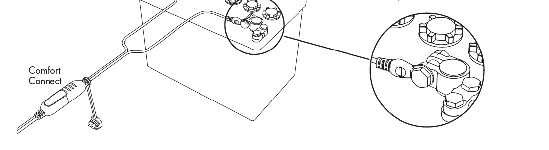
The picture in bottom right clearly shows the battery post connected to the negative chassis cable, so the battery must be in situ in the car and they have the charger by passing the sensor. The manual’s wording is rather confusing and does seem to conflict with the diagram, agreed.
Surely the charge counting is only useful within the actual charger to control the charge rate and temperature protection and not within the cars BMS. The car’s BMS has no control on the external charger’s charge rate so can’t stop any damage if a badly designed charger is connected (Say too high current/over voltage gassing or over heating etc). That’s why I’m thinking Mazda simply checks the standing voltage and temperature after at least several hours left idle or just before the car is actually started to detemine if it’s a healthy enough SOC for the i-Stop etc?
By being attached to the chassis the charge current must pass through the sensor. Whether it is measured or not is another question. If you wanted to by-pass the sensor you would need to connect directly to the battery post.
EDIT However I take your point in the next diagram of the flying lead connection. This just supports my view that they aren’t trying to say anything about the charge sensing, it’s purely about avoiding arcing at the battery.
Agreed. Also CTEK has no idea on the user’s car make and model, whether it has a current sensor or not or if the car is equipped with i-Stop or not etc.
But also per RichardFX comments, charging via the current sensor does pose a risk to confusing the car’s BMS, especially if the external charger is poorly designed and say overheats the battery giving the sensor an overly high temperature reading if you tried starting the engine soon after removing the external charger.