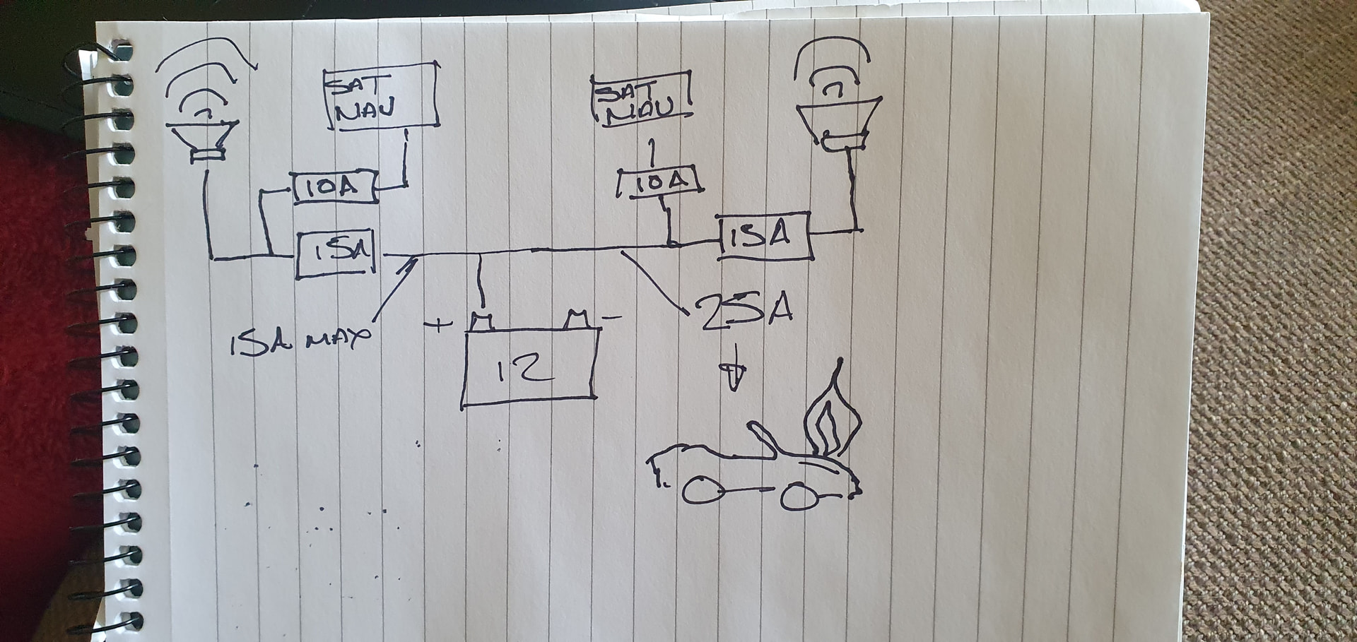
I’ve drawn it for you.
Thanks Nick, I genuinely appreciate your input- the problem is me, I’m just not fully understanding what I’m doing. I’m not arguing with you, I’m not in a position to do so as I’m just confused![]()
I pulled the original fuse out and used the multimeter to determine which terminal in the fuse box is live. I believe the piggyback goes in with the wire tail furthest from that side - so the current flows through the fuse before getting to the accessory, thus protecting it.
So the way I have it now the piggyback is in with the wire tail furthest from that live side.
In this position, if I remove just the original fuse, the accessory still works- and this is the crux of the matter as I don’t know if this is desirable or not.
Sorry to be a bit dim- just confused and somewhat concerned.
In desperation I asked Chat GPT the “crux question “, on two separate occasions, and got 2 different answers…….. interesting observation on our apparently increasing dependence on AI??
1. ✅ The correct / desirable setup is:
The accessory should STILL work even if the original fuse is removed.
That means the piggyback is installed correctly.
2. When using a piggyback (add-a-fuse) tap, the preferred and safer setup is:
![]() If the original fuse is removed, the accessory should also stop working.
If the original fuse is removed, the accessory should also stop working.
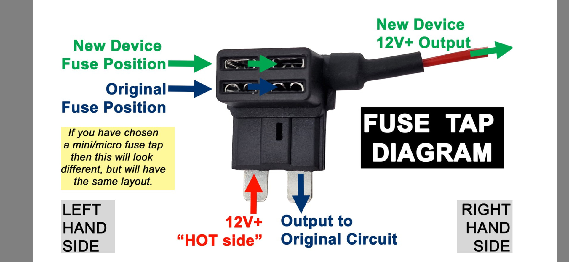
Important notice about the correct orientation of a piggyback fuse:
**This explains the orientation I have the p/b fuse at present :
“Installing the p/b the wrong way round can be a safety hazard!”
( Hence my concern!!)
In the fusebox
there are two points, that the bottom contacts of the fuse plug in to:
1. The hot side (12v+)
2. The device side - no voltage (this leads to the original device/circuit being protected)
On the new p/b the side with the red wire connected should be installed in to the device side slot (the side with no voltage present).
If you were to accidentally install this side on the “hot” side, the new device would receive power without trav-elling through the fuse (a big safety risk!).
AGAIN- NOT CLAIMING IM RIGHT- JUST CONFUSED!
This is correct.
What this picture is showing is the bottom blades go into the fuse box where the fuse originally went, oriented so that the output wire to your new accessory is the opposite side of the blade you are going to pug into the terminal you have identified as the hot side. I think you wrote earlier that that side was towards out outside of the car.
The original 15A fuse then goes in the lower slot and the new accessory fuse goes in the upper slot.
Within that block, the right hand lower socket should connect with the left hand upper socker to make all this work. Removing the lower fuse should kill the upper circuit.
If it does not then the block is not suitable and you would need to instal an in-line fuse in the “New Device 12V output” line after this block.
Thanks for that message.
So, the way I have the P/B fuse oriented at present is as per my last photo- the blade without the wire is into the live side of the fuse aperture and the blade with the wire tail is on the other side.
- In this position, with the original fuse only removed the accessory still works- this tells me current is flowing through the accessory fuse even though the original fuse is absent.
- Also in this position, with the accessory fuse absent, (obviously?) the accessory doesn’t work.
In my (simple) mind I therefore take those two statements to mean as follows:
Inserted in this way, current is flowing through the accessory fuse to the accessory . And current is flowing through the original fuse to the items it serves. THUS BOTH CIRCUITS ARE PROTECTED AS CURRENT IS FLOWING THROUGH THE FUSES IN BOTH CASES, TO THEIR RESPECTIVE LOADS. Orig fuse is 15A and accessory is 3A.
IF THE ACCESSORY DIDNT WORK WHEN THE ORIGINAL FUSE WAS REMOVED IT WOULD TELL ME THE ACCESSORY IS POWERED BY CURRENT PASSING THROUGH THE ORIGINAL FUSE, AS OPPOSED TO THROUGH THE ACCESSORY FUSE- and again ( in my simple mind) this is undesirable.
Still somewhat shocked that Chat GPT gives me 2 different answers to the same question…….. worrying.
Glad you like THIS:
Thanks for persevering with me.
David
Your connection is wrong as is your logic. ALL current MUST go through the original fuse. (This is to protect the cars wiring loom prior to the fuse) If you remove the main fuse and you have it wired correctly EVERYTHING will be dead.
![]()
Back to the drawing board then.![]()
![]()
I still believe the blade without the wire tail should be connected to the hot or live side of the fuse box as per:
I will buy another piggyback tomorrow and see if it behaves differently.
Nick did seem to agree the above diagram iscorrect, but the P/B I have may not be suitable?
Using the above, if pulling the ‘original fuse position’ does not disable both circuits then I would be extremely careful about the load that you put through the ‘new device output’.
The fuse is to protect the wiring before the ‘hot side’, if the ‘new device output’ is still live then you have the ability to put the original load PLUS the additional load through the wiring circuit prior to the ‘hot side’. This could potentially overload the wiring prior to the ‘hot side’ and result in a ‘problem’.
![]()
Thanks Malc , this makes sense, even to my simple mind……..
I’d be grateful if you would have a look at the below : it’s a summary of my thoughts and I conclude I must have a “Parallel” piggy-back, ( the most common).
**So, it would appear there are 2 designs of piggy-back fuse, and this along with the possibility of reversed insertion, may give rise to the confusion which arises from visiting different internet sites/Utube videos etc.
- Parallel Design- which I believe I have
Hot terminal to (original) 15 A fuse and factory circuit
and
Hot terminal to 3 A (accessory) fuse and accessory
ie the no wire blade to the hot side of the fuse box .
NB : Remove original fuse, accessory STILL WORKS
- Series Design
NB : in this case- remove original fuse, EVERYTHING stops
I think this is the design many on-line guides assume, which is why they say removing the original fuse should kill the accessory.
- Reversed installation
ie, the blade with the wire inserted into the hot terminal (before the fuse). This is obviously unsafe.
So, my current situation: PARALLEL
Non-wire blade to live terminal (hot)
Wire blade to load side.
Removal of 15 A (original) fuse does not kill accessory.
THIS FITS WITH 1. ABOVE, the PARALLEL design , which is normal and safe for a small load like a phone charger
Heading out for a walk with the dogs- need to clear the head!
Have a look here Bing Videos it may help.
Just put the piggy back in the opposite way round then all the load goes through the original fuse and if you pull it, both circuits die.
You MUST ensure that the total maximum amps drawn by both wires is at or below the original fuse rating.
Safest is to take a new wire direct from the battery with it’s own inline fuse, both of which should be of the correct rating for the accessory you are fitting. (As I did when fitting air horns to the ND)
![]()
Thanks for this ![]()
Does the diagram below help?
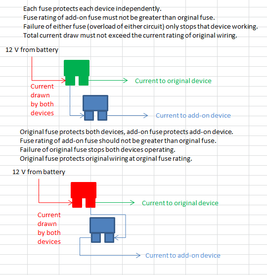
In the top arrangement the fuses are connected in parallel with each other, in the lower arrangement the fuses are connected in series.
Of course, without knowing the actual current carrying capacity of the original wiring it’s all a moot point anyway, the fuse rating will be well above the continuous current carrying capacity of the wiring…
…but without knowing the specific application, I’d guess that the NC MX-5 has the live side of the fuses connected by a bus bar within the fuse box, so overloading the supply side of the circuit is unlikely. I’d choose the top arrangement if it were me.
Thanks for this Robbie.
Your choice (top one in your post) looks like my (current) choice- no pun intended.
non-wire blade into hot side of the fuse box.
Blade with wire tail into “load” side of fuse box.
As you say this is a PARALLEL circuit.
*Each fuse protects each device independently
*Current drawn by both devices - So removal of original fuse won’t disable the accessory.
As you say:
“Each fuse protects each device independently.”
“Fuse rating of add-on fuse must not be greater than orginal fuse.” In my case, orig fuse is 15amp, and add-on is 3amp
“Failure of either fuse (overload of either circuit) only stops that device working.”
“Total current draw must not exceed the current rating of original wiring.” In my case I have the new USB/phone charger socket ( in the dash-top speaker grille) for the purposes of plugging in an old iPhone which I use as sat-nav. Such an adapter typically supplies 5V at 1A–2A. My accessory circuit is protected by a 3amp fuse.
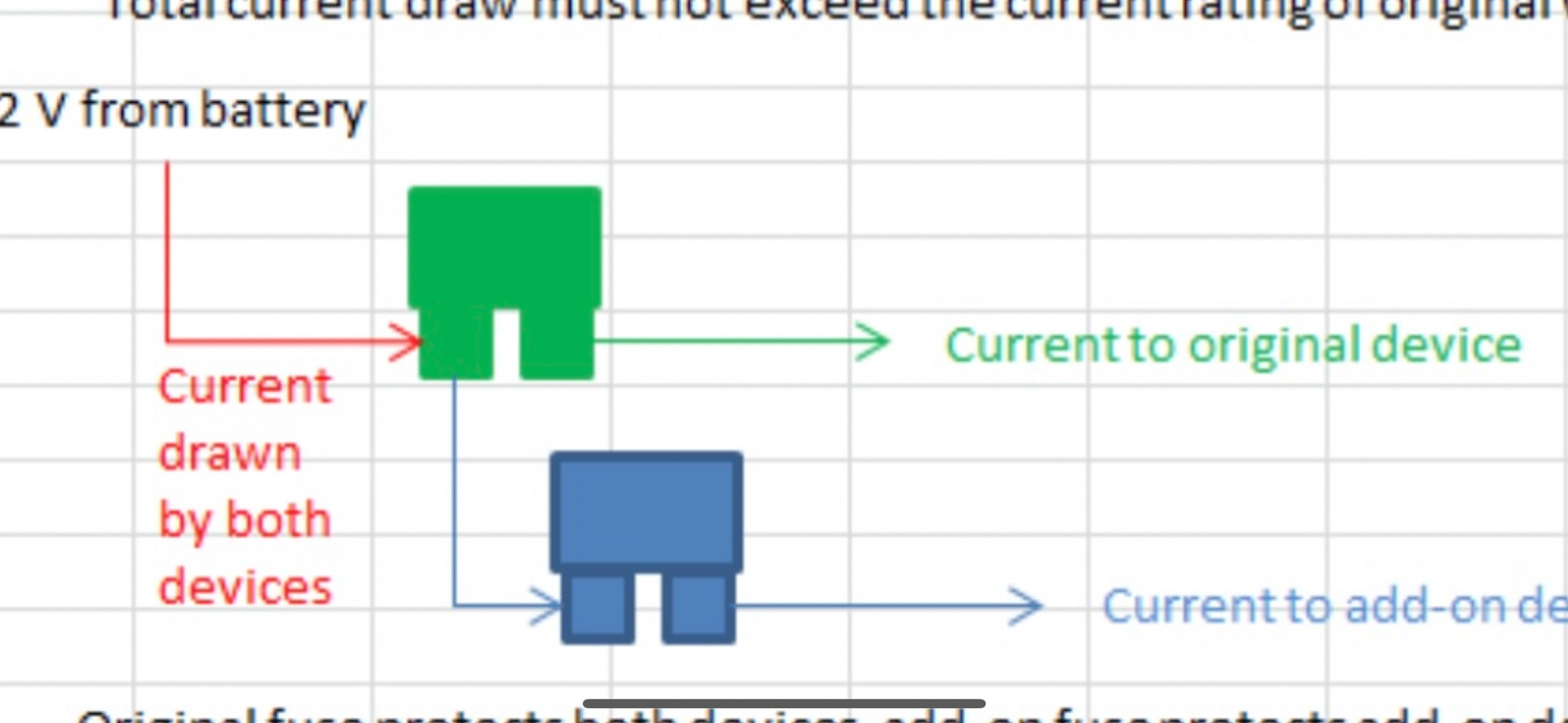
I think your top diagram looks like this:
PLEASE CORRECT ME IF I’M WRONG
1 Like
I think you are now just going round in circles, you have had all the information you need to make an informed decision as what you can do and feel happy with.
![]()
1 Like
Have done so- thanks- have you?
Hope the “circles” help someone else, and at least create an awareness of the issue- many folk just plug it in…..
![]()
Yes, my top diagram is the same layout as the one in the photo.
All of this has blown my head but has been very helpful.
Only question I have, and apologies if it’s a stupid one, how do I determine the live side of the fuse holder?
![]() Thanks
Thanks