Hi & I hope that this is in the right forum (if not my excuse is that this is my first posting!)
Having just fitted an autodimming rear view mirror & glove box light to my 59 plate MX-5 Roadster Coupe - I realise that there wasn’t a comprehensive guide on how to do this on the web, so have created such a guide, in the hope that it’s of value to someone else.
All the work was done with roof down for ease of access. Total time taken about 3 hours.
1. Remove original mirror
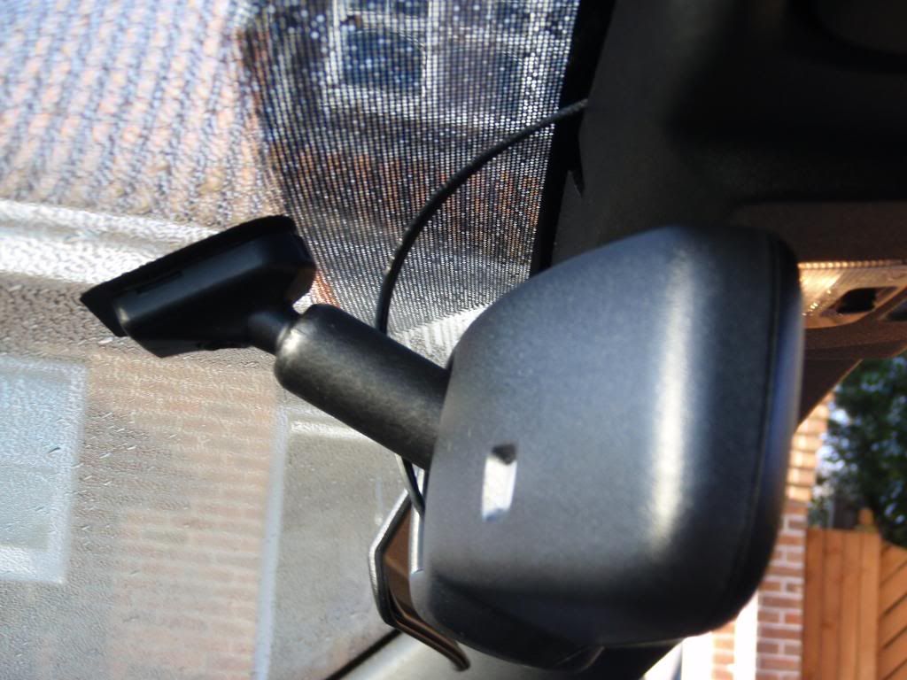
a. <v:shapetype coordsize=“21600,21600” o:spt=“75” o:preferrelative=“t” path=“m@4@5l@4@11@9@11@9@5xe” filled=“f” stroked=“f” id="_x0000_t75"><v:stroke joinstyle=“miter”></v:stroke><v:formulas><v:f eqn=“if lineDrawn pixelLineWidth 0”></v:f><v:f eqn=“sum @0 1 0”></v:f><v:f eqn=“sum 0 0 @1”></v:f><v:f eqn=“prod @2 1 2”></v:f><v:f eqn=“prod @3 21600 pixelWidth”></v:f><v:f eqn=“prod @3 21600 pixelHeight”></v:f><v:f eqn=“sum @0 0 1”></v:f><v:f eqn=“prod @6 1 2”></v:f><v:f eqn=“prod @7 21600 pixelWidth”></v:f><v:f eqn=“sum @8 21600 0”></v:f><v:f eqn=“prod @7 21600 pixelHeight”></v:f><v:f eqn=“sum @10 21600 0”></v:f></v:formulas><v:path o:extrusionok=“f” gradientshapeok=“t” o:connecttype=“rect”></v:path><o:lock v:ext=“edit” aspectratio=“t”></o:lock></v:shapetype>It appears that this is held on by springs either side of the mount – see image of original mirror base mount below:
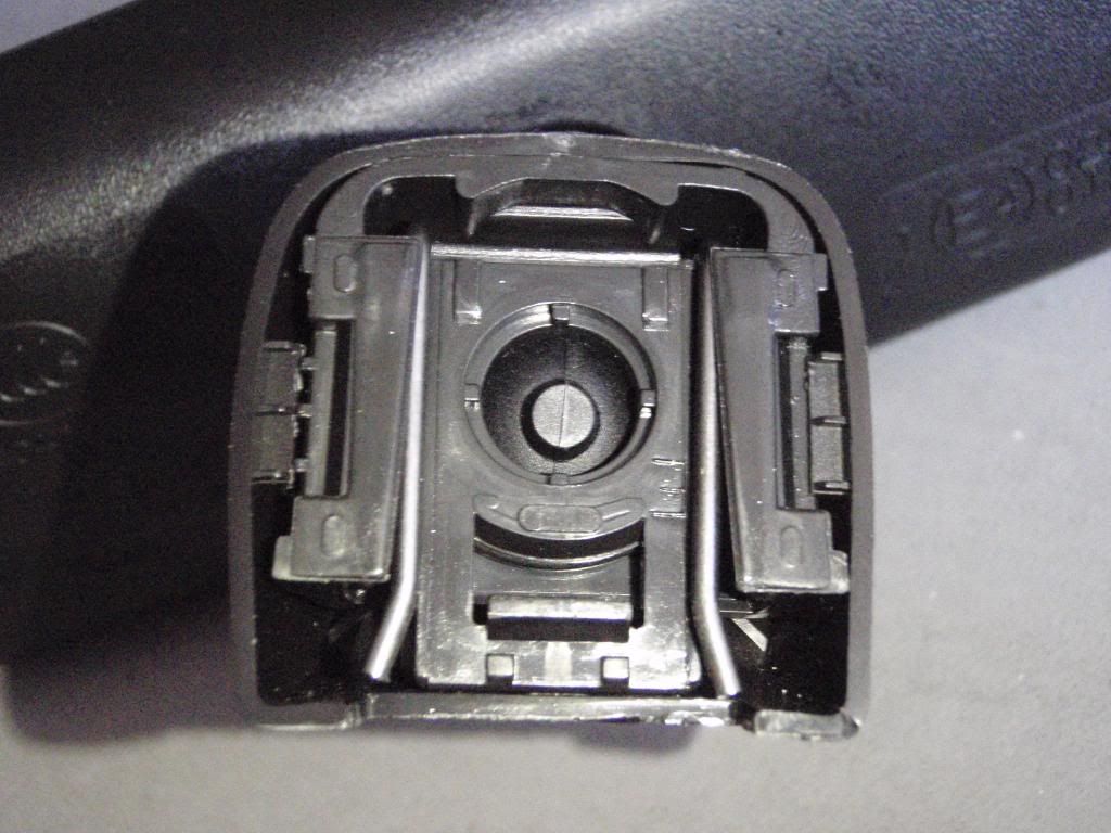
b. Push up from below, using a flat blade screw driver to release catch. This is a fiddle and gently forceful side to side wiggle seemed to help!
2. The windscreen mount thus looks like: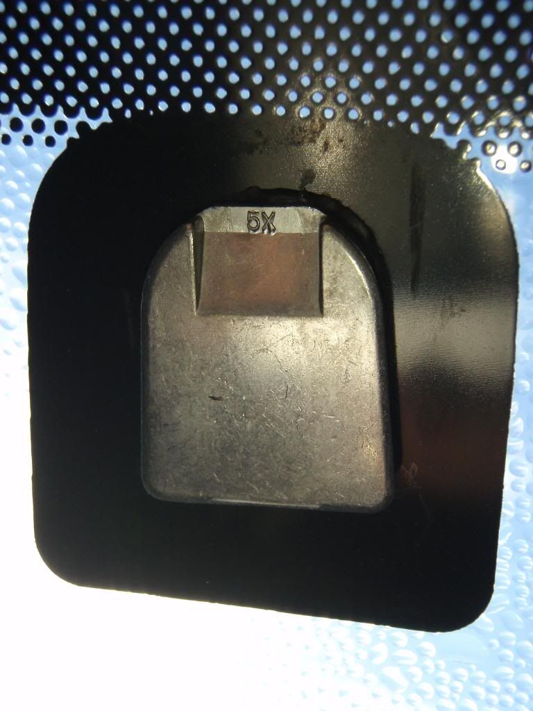
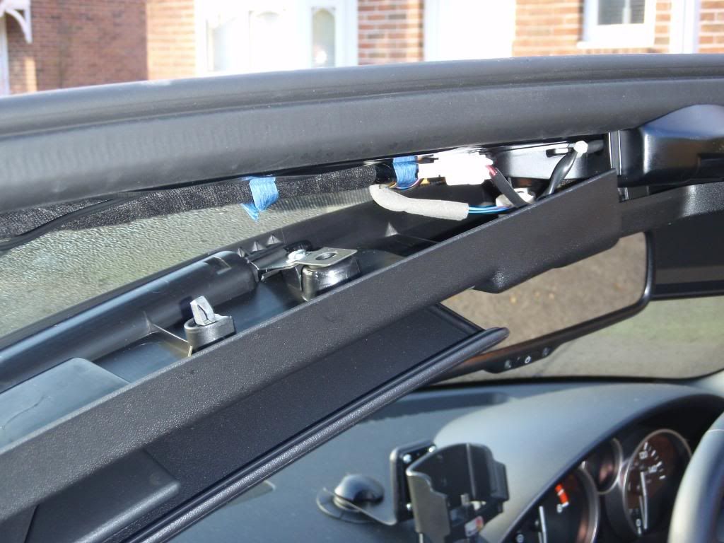
3. Remove the windscreen header trim torx screws – one under the sun visor, two under the roof alignment piece on the left hand side only.
4. Remove the A pillar trim – this pulls out towards the centre of the car, held on by clips.
5. <v:shapetype coordsize=“21600,21600” o:spt=“75” o:preferrelative=“t” path=“m@4@5l@4@11@9@11@9@5xe” filled=“f” stroked=“f” id="_x0000_t75"><v:stroke joinstyle=“miter”></v:stroke><v:formulas><v:f eqn=“if lineDrawn pixelLineWidth 0”></v:f><v:f eqn=“sum @0 1 0”></v:f><v:f eqn=“sum 0 0 @1”></v:f><v:f eqn=“prod @2 1 2”></v:f><v:f eqn=“prod @3 21600 pixelWidth”></v:f><v:f eqn=“prod @3 21600 pixelHeight”></v:f><v:f eqn=“sum @0 0 1”></v:f><v:f eqn=“prod @6 1 2”></v:f><v:f eqn=“prod @7 21600 pixelWidth”></v:f><v:f eqn=“sum @8 21600 0”></v:f><v:f eqn=“prod @7 21600 pixelHeight”></v:f><v:f eqn=“sum @10 21600 0”></v:f></v:formulas><v:path o:extrusionok=“f” gradientshapeok=“t” o:connecttype=“rect”></v:path><o:lock v:ext=“edit” aspectratio=“t”></o:lock></v:shapetype>Pull down on the windscreen header trim at the left end – it will flex in the middle – and is held in place by clips. No need to remove right hand side.
6. Remove the door seal trim on the left side.
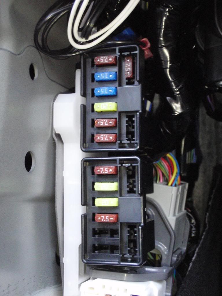
7. Remove the fuse cover and then remove the fuse panel itself – there are two clips, one black one at the bottom of this piece and a white one under the cover. Removing the sill cover aids here – this pulls upward to unclip. The fuse panel removes by pulling towards the centre of the car.
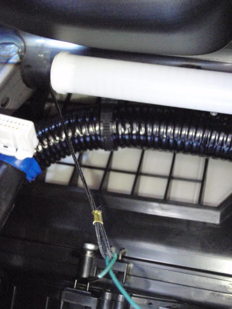
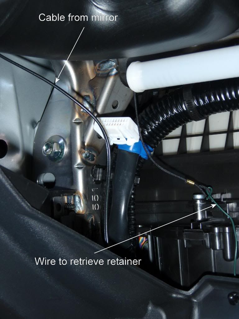
8. I found it easier to remove the glove box at this point. Undo the tie on the left side connecting the glove box to the damper (white tubular piece) but retain it with a length of wire. Press both sides inwards to release and the glove box will release when dropped down.
9. Fit the new auto dimming rear view mirror - a Gentex Genk2 – to the windscreen mount. This fits over the original mount with no modification. Tighten the torx screw on the base mounting to secure when doing the final reassembly.
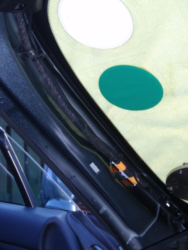
10. <v:shapetype coordsize=“21600,21600” o:spt=“75” o:preferrelative=“t” path=“m@4@5l@4@11@9@11@9@5xe” filled=“f” stroked=“f” id="_x0000_t75"><v:stroke joinstyle=“miter”></v:stroke><v:formulas><v:f eqn=“if lineDrawn pixelLineWidth 0”></v:f><v:f eqn=“sum @0 1 0”></v:f><v:f eqn=“sum 0 0 @1”></v:f><v:f eqn=“prod @2 1 2”></v:f><v:f eqn=“prod @3 21600 pixelWidth”></v:f><v:f eqn=“prod @3 21600 pixelHeight”></v:f><v:f eqn=“sum @0 0 1”></v:f><v:f eqn=“prod @6 1 2”></v:f><v:f eqn=“prod @7 21600 pixelWidth”></v:f><v:f eqn=“sum @8 21600 0”></v:f><v:f eqn=“prod @7 21600 pixelHeight”></v:f><v:f eqn=“sum @10 21600 0”></v:f></v:formulas><v:path o:extrusionok=“f” gradientshapeok=“t” o:connecttype=“rect”></v:path><o:lock v:ext=“edit” aspectratio=“t”></o:lock></v:shapetype>Plug the cable socket into the mirror. The cable can be taped to the mirror arm. A cable cover from the mount to the header can be purchased separately (not used here as the cable can’t be seen from the outside). Run the cable up into the windscreen header (there is a convenient cut out in the middle) and run along the original cable bundle.
11. Run the cable down the original cable bundle in the A pillar using cable ties & tape to secure.
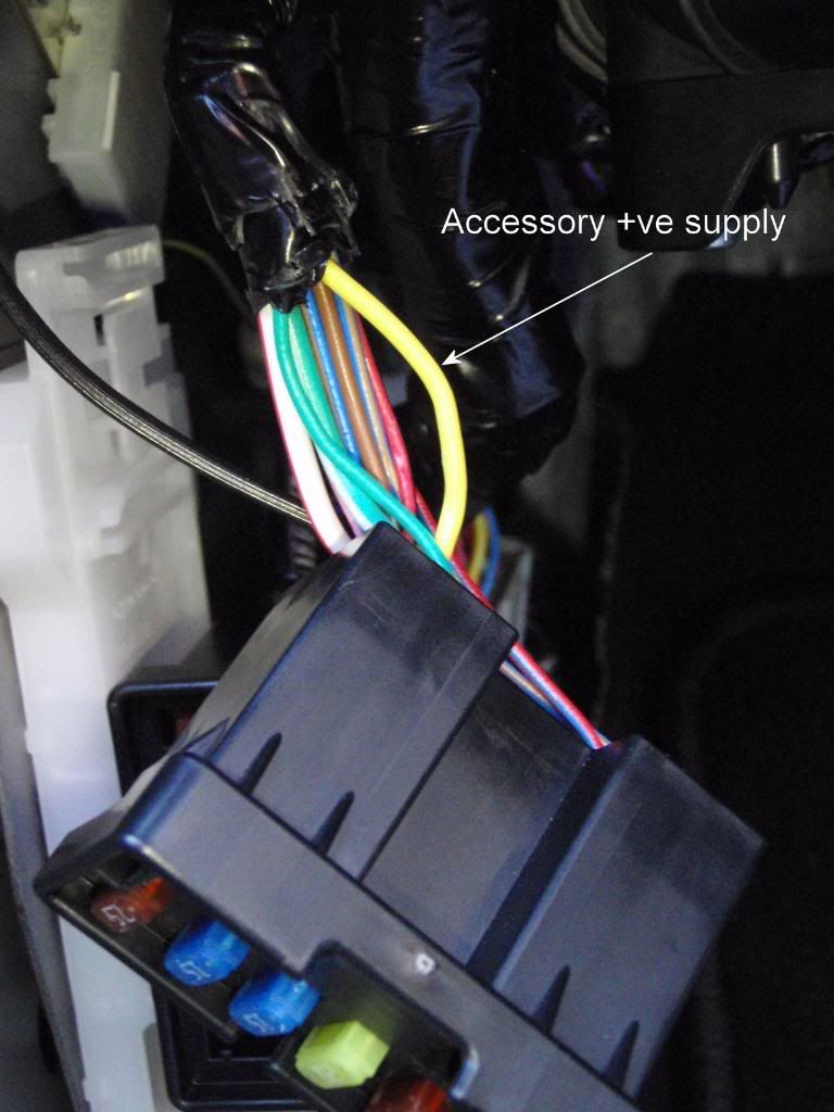
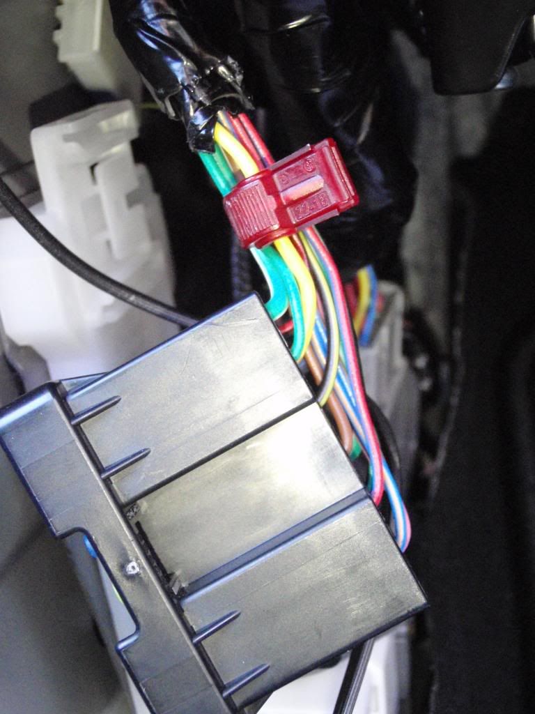
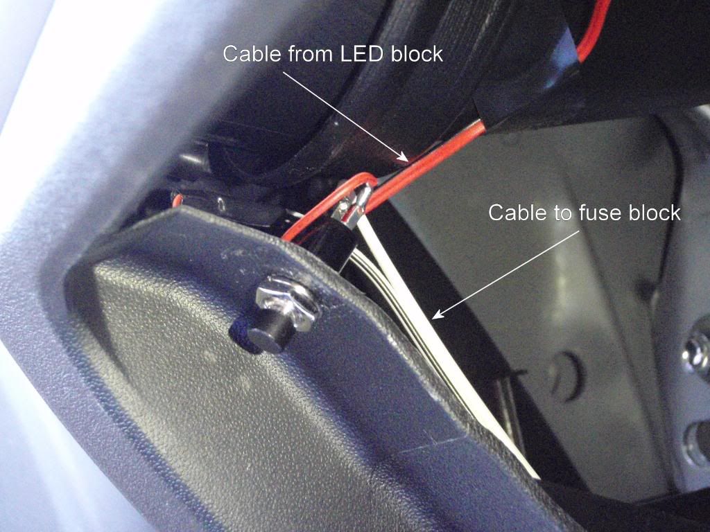
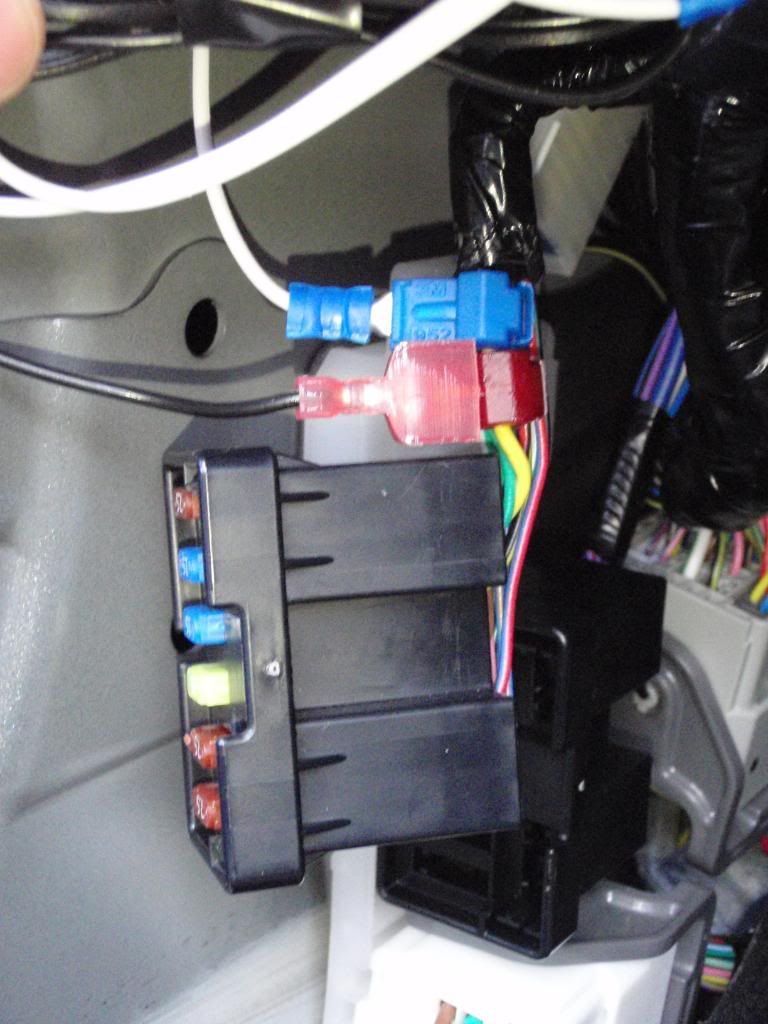
13. Wire the mirror cable to the fuse box. I used the accessory fuse which is the second one down from the top in the top block. The top block of fuses can be removed by sliding the black block forwards on the white mount. This makes it much easier to access the cable at the back. The positive supply cable is the yellow cable to the second fuse from the top. Clear away the black cable tape to expose.
14. <v:shapetype coordsize=“21600,21600” o:spt=“75” o:preferrelative=“t” path=“m@4@5l@4@11@9@11@9@5xe” filled=“f” stroked=“f” id="_x0000_t75"><v:stroke joinstyle=“miter”></v:stroke><v:formulas><v:f eqn=“if lineDrawn pixelLineWidth 0”></v:f><v:f eqn=“sum @0 1 0”></v:f><v:f eqn=“sum 0 0 @1”></v:f><v:f eqn=“prod @2 1 2”></v:f><v:f eqn=“prod @3 21600 pixelWidth”></v:f><v:f eqn=“prod @3 21600 pixelHeight”></v:f><v:f eqn=“sum @0 0 1”></v:f><v:f eqn=“prod @6 1 2”></v:f><v:f eqn=“prod @7 21600 pixelWidth”></v:f><v:f eqn=“sum @8 21600 0”></v:f><v:f eqn=“prod @7 21600 pixelHeight”></v:f><v:f eqn=“sum @10 21600 0”></v:f></v:formulas><v:path o:extrusionok=“f” gradientshapeok=“t” o:connecttype=“rect”></v:path><o:lock v:ext=“edit” aspectratio=“t”></o:lock></v:shapetype>Apply the supplied red T-Tap connector to this yellow cable.
15. For the negative ground I used the bolt holding the fan assembly.
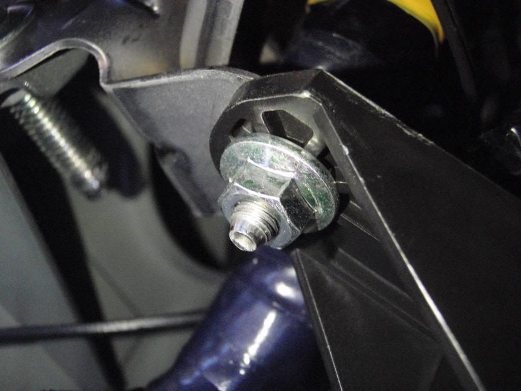
16. Connect the red spade connector to the red T-Tap connector and the blue ring connector to the bolt (10mm spanner/socket).
17. Test the mirror is functioning by turning the ignition switch & check that the green LED to the left of the mirror power switch illuminates.
18. As the glove box area was exposed I decided to fit a glove box light at this point. If this is not required then ignore the next bit & replace everything!
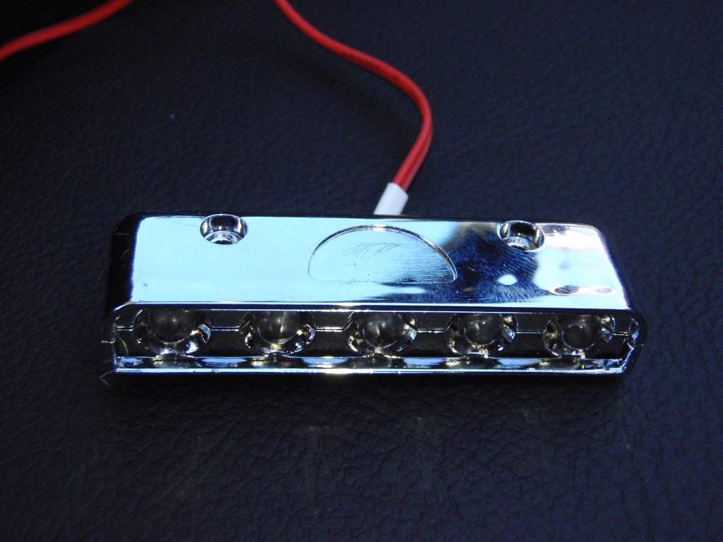
19. The light source was a 5 bulb LED block.
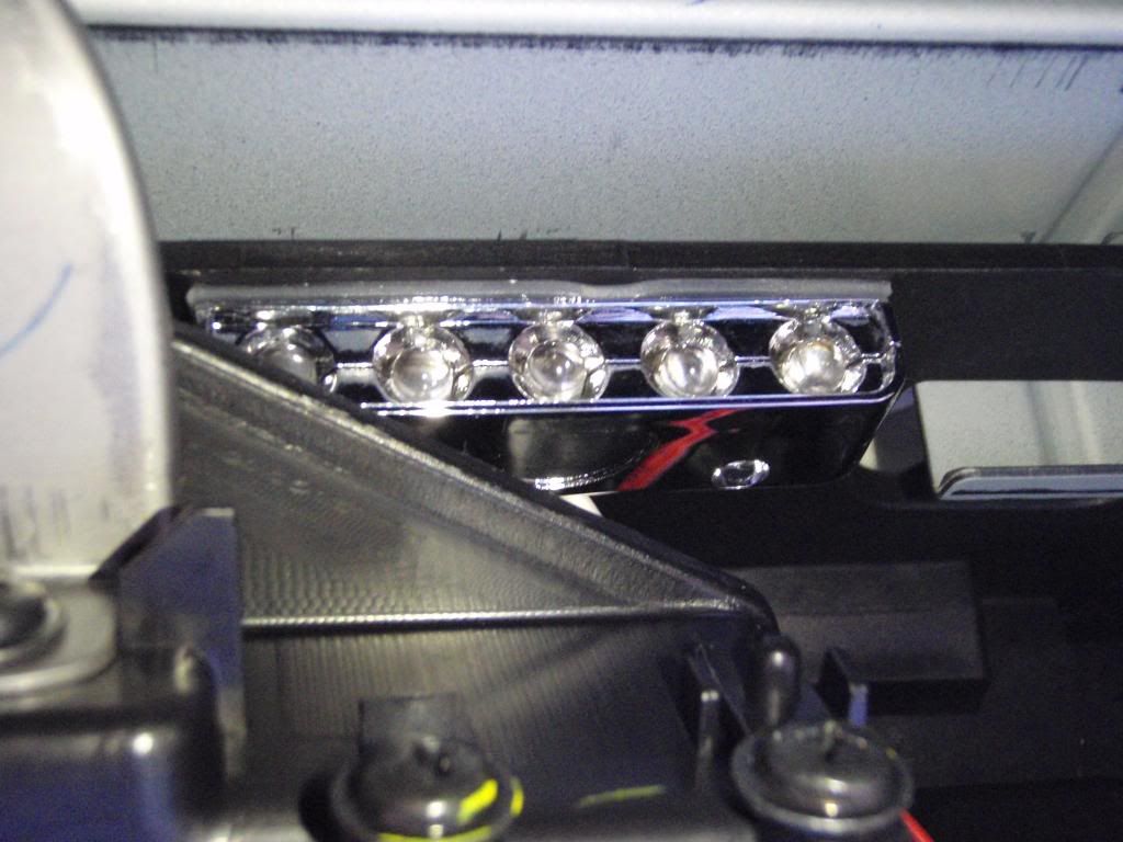
20. <v:shapetype coordsize=“21600,21600” o:spt=“75” o:preferrelative=“t” path=“m@4@5l@4@11@9@11@9@5xe” filled=“f” stroked=“f” id="_x0000_t75"><v:stroke joinstyle=“miter”></v:stroke><v:formulas><v:f eqn=“if lineDrawn pixelLineWidth 0”></v:f><v:f eqn=“sum @0 1 0”></v:f><v:f eqn=“sum 0 0 @1”></v:f><v:f eqn=“prod @2 1 2”></v:f><v:f eqn=“prod @3 21600 pixelWidth”></v:f><v:f eqn=“prod @3 21600 pixelHeight”></v:f><v:f eqn=“sum @0 0 1”></v:f><v:f eqn=“prod @6 1 2”></v:f><v:f eqn=“prod @7 21600 pixelWidth”></v:f><v:f eqn=“sum @8 21600 0”></v:f><v:f eqn=“prod @7 21600 pixelHeight”></v:f><v:f eqn=“sum @10 21600 0”></v:f></v:formulas><v:path o:extrusionok=“f” gradientshapeok=“t” o:connecttype=“rect”></v:path><o:lock v:ext=“edit” aspectratio=“t”></o:lock></v:shapetype>This was fitted up behind the locking mechanism using double sided tape.
21. <v:shapetype coordsize=“21600,21600” o:spt=“75” o:preferrelative=“t” path=“m@4@5l@4@11@9@11@9@5xe” filled=“f” stroked=“f” id="_x0000_t75"><v:stroke joinstyle=“miter”></v:stroke><v:formulas><v:f eqn=“if lineDrawn pixelLineWidth 0”></v:f><v:f eqn=“sum @0 1 0”></v:f><v:f eqn=“sum 0 0 @1”></v:f><v:f eqn=“prod @2 1 2”></v:f><v:f eqn=“prod @3 21600 pixelWidth”></v:f><v:f eqn=“prod @3 21600 pixelHeight”></v:f><v:f eqn=“sum @0 0 1”></v:f><v:f eqn=“prod @6 1 2”></v:f><v:f eqn=“prod @7 21600 pixelWidth”></v:f><v:f eqn=“sum @8 21600 0”></v:f><v:f eqn=“prod @7 21600 pixelHeight”></v:f><v:f eqn=“sum @10 21600 0”></v:f></v:formulas><v:path o:extrusionok=“f” gradientshapeok=“t” o:connecttype=“rect”></v:path><o:lock v:ext=“edit” aspectratio=“t”></o:lock></v:shapetype>A small push to break switch (Maplin FH60Q)was fitted to the top left side of the glove box opening so that the rubber plug on the top left corner of the glove box would activate it on closure.
22. Solder the positive lead from the LED block to the switch (before fitting!) and add sufficient cable to reach down to the fuse box.
23. Fit a spade end to the positive wire and a ring end to the negative wire.
24. Use the spare blue T-Tap connector from the mirror kit & fit next to the red T-Tap connector on the yellow cable. Fit the spade connector on the positive wire to this T-Tap connector.
26. Check the LED bulbs are lit, confirm the switch turns them off when pressed.
27. Replace the fuse block on its mount & tidy away the cables.
27. Replace the fuse panel & cover. Replace the sill trim, and door seal trim.
28. Replace the A pillar trim.
29. Replace the windscreen header trim – this will need firm upward pressure to replace the clips.
30. Replace & tighten the torx screw under the visor. Replace the roof alignment piece and the two torx screws – leave loose at this point.
31. Close the roof, ensure a correct fit with the roof alignment piece then tighten the two torx screws.
32. Replace the glove box – the reverse of removal. Use the wire to retrieve the damper cord & refit to the fixing on the left side of the glove box.
33. <v:shapetype coordsize=“21600,21600” o:spt=“75” o:preferrelative=“t” path=“m@4@5l@4@11@9@11@9@5xe” filled=“f” stroked=“f” id="_x0000_t75"><v:stroke joinstyle=“miter”></v:stroke><v:formulas><v:f eqn=“if lineDrawn pixelLineWidth 0”></v:f><v:f eqn=“sum @0 1 0”></v:f><v:f eqn=“sum 0 0 @1”></v:f><v:f eqn=“prod @2 1 2”></v:f><v:f eqn=“prod @3 21600 pixelWidth”></v:f><v:f eqn=“prod @3 21600 pixelHeight”></v:f><v:f eqn=“sum @0 0 1”></v:f><v:f eqn=“prod @6 1 2”></v:f><v:f eqn=“prod @7 21600 pixelWidth”></v:f><v:f eqn=“sum @8 21600 0”></v:f><v:f eqn=“prod @7 21600 pixelHeight”></v:f><v:f eqn=“sum @10 21600 0”></v:f></v:formulas><v:path o:extrusionok=“f” gradientshapeok=“t” o:connecttype=“rect”></v:path><o:lock v:ext=“edit” aspectratio=“t”></o:lock></v:shapetype>Finished mirror!
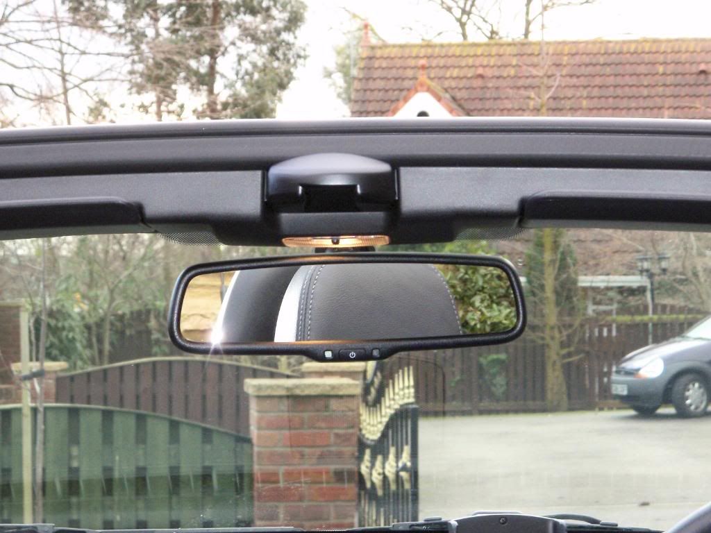
It is marginally larger (by the size of the surround) than the original. However when correctly angled neither visor catches it.
Much better than getting blinded then having to manually change the mirror (then forget to change it back & wonder why I can’t see!)
