Haldex Pump ( freelander 2 ) Advice Sought

Hi All
If any of you electrical gurus ( Rhino ? ) can point me in the right direction I would be very greatfull !

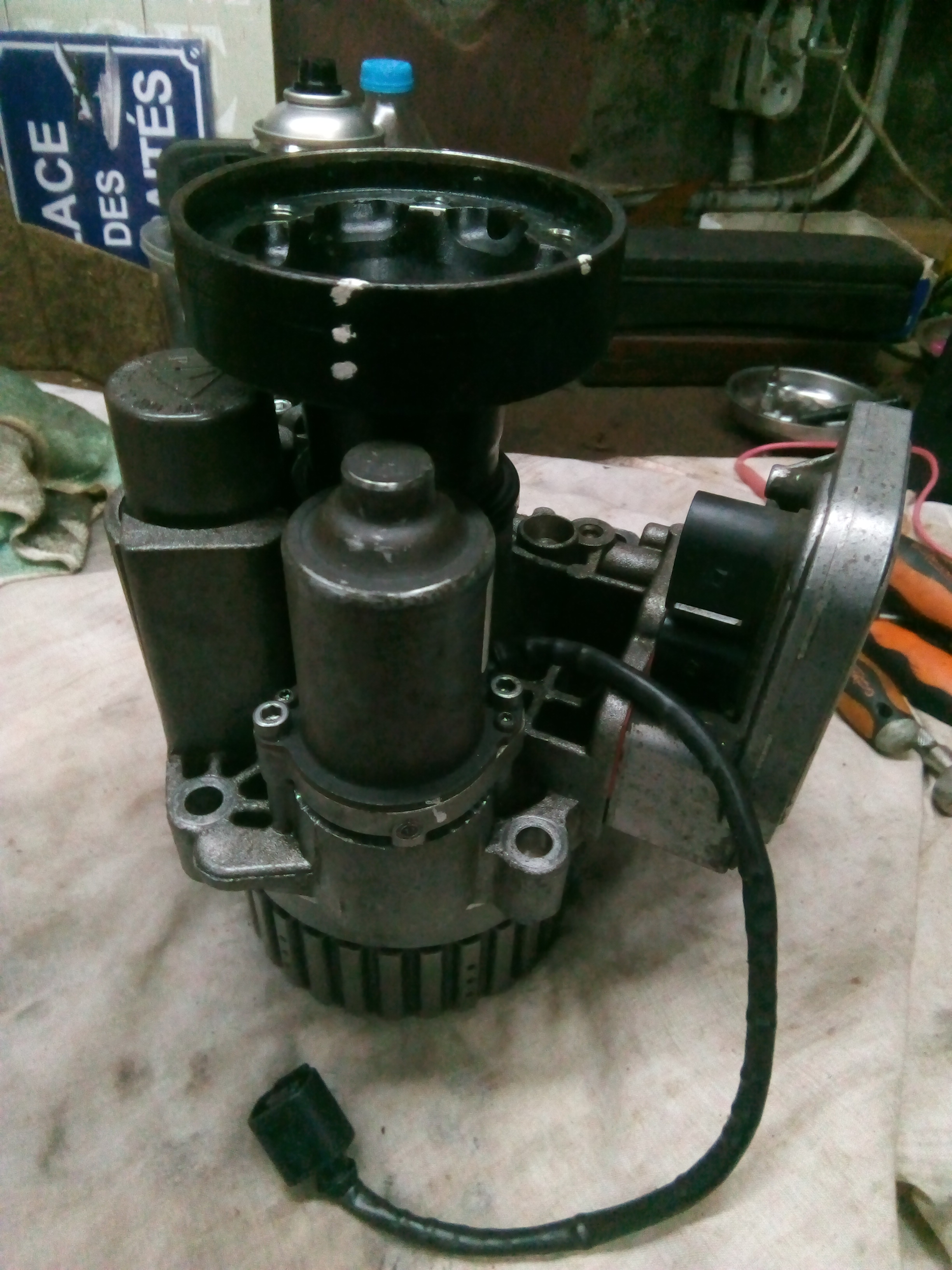
Servicing the haldex on my new to me Freelander 2 TD4. My question relates to the resistance in ohms of the pump.

From searching forums and reading advice at Haldex specialist websites, it seems the resistance of a good working haldex pump fitted to the Freelander 2 ( live and ground ) should be between 5-8 ohms.

Not much actual information on Landrover owners sites from individuals experience.

However there is a lot of information on other owners sites ( mainly VW, Audi, Skoda etc ). The experience there seems to dictate that most people get a reading of around 2.2 - 2.5 ohms at the connector.

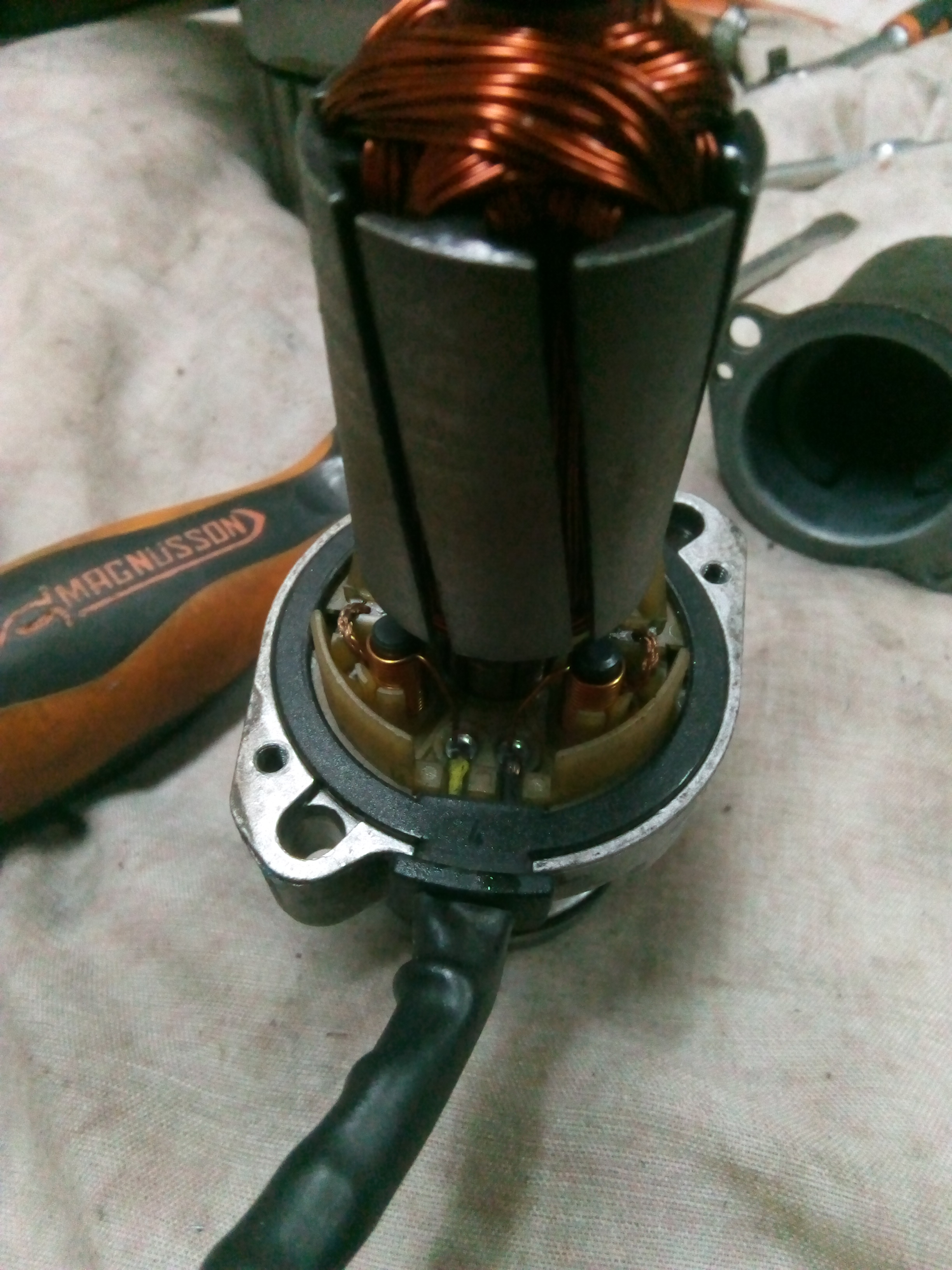
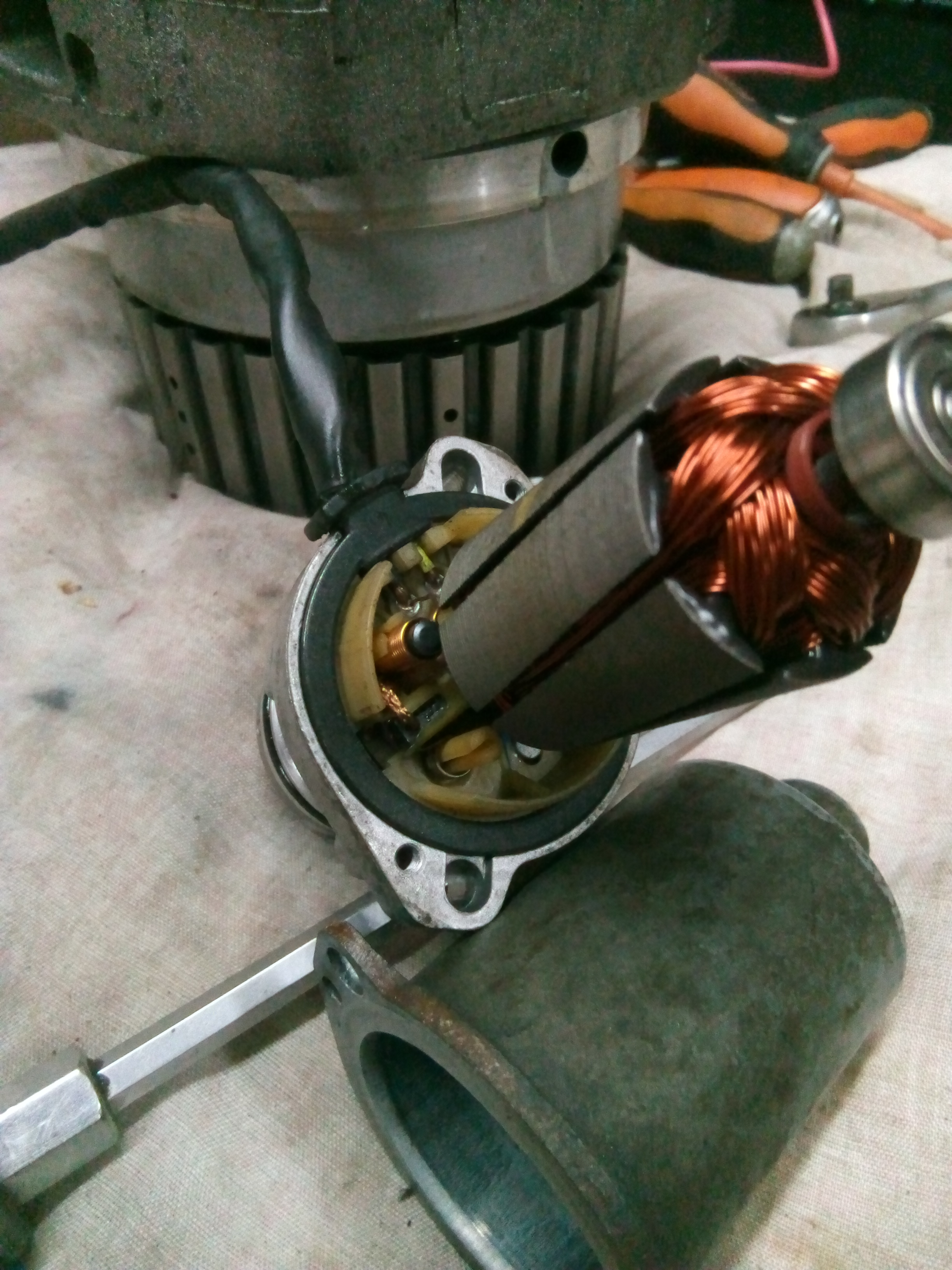
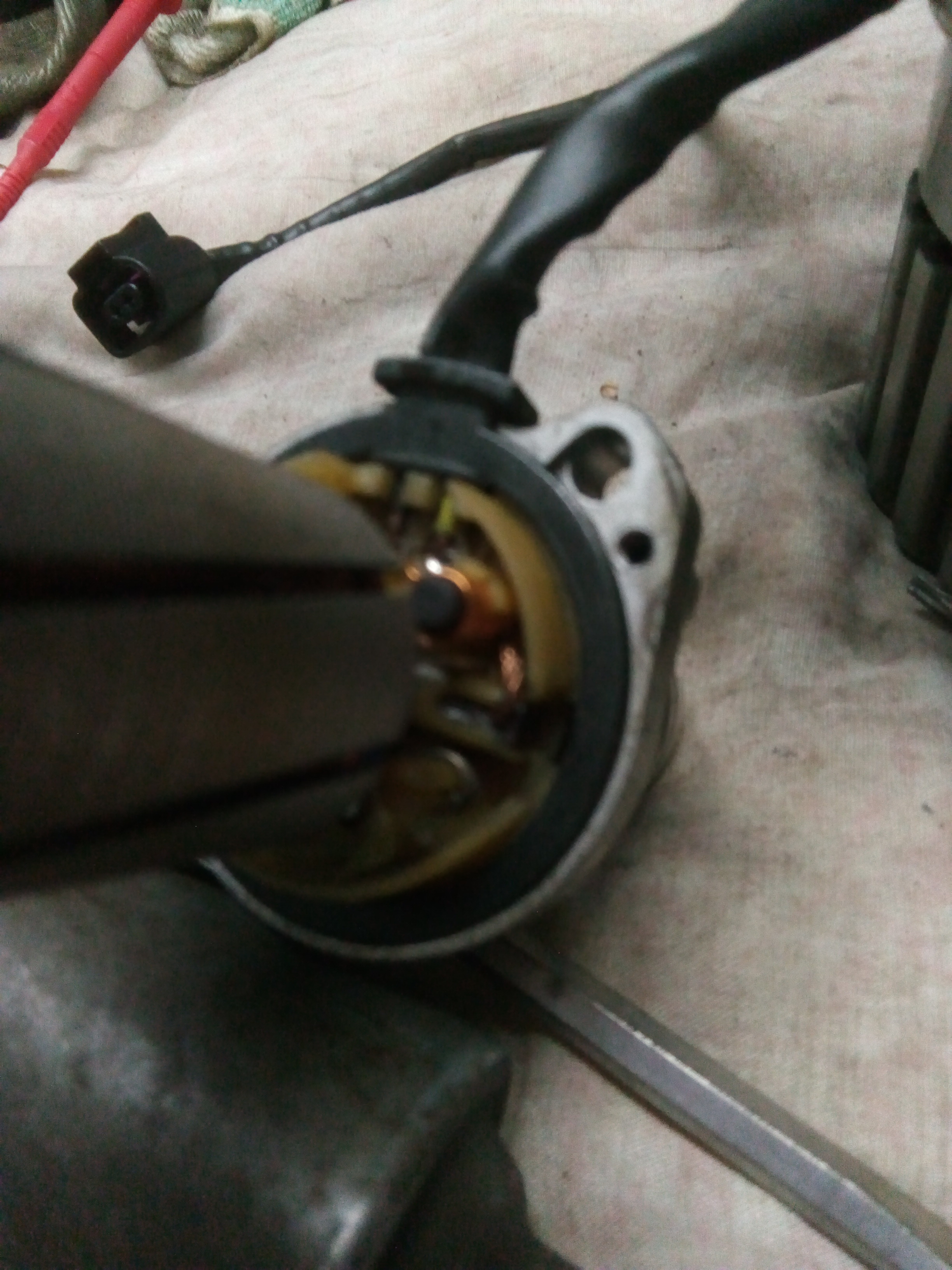
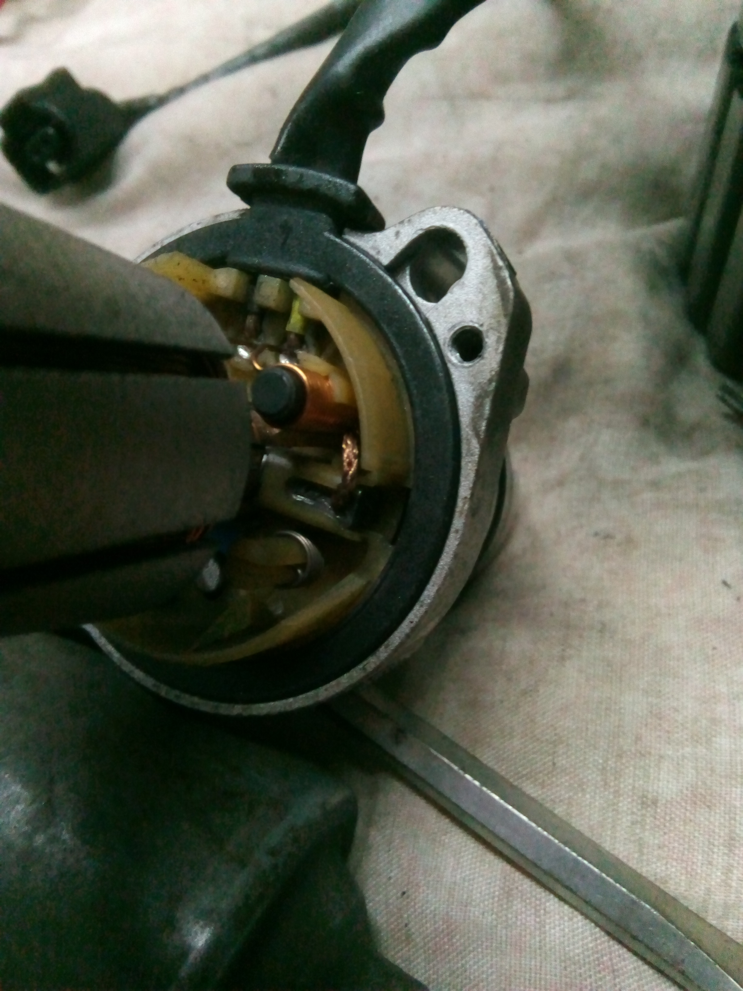
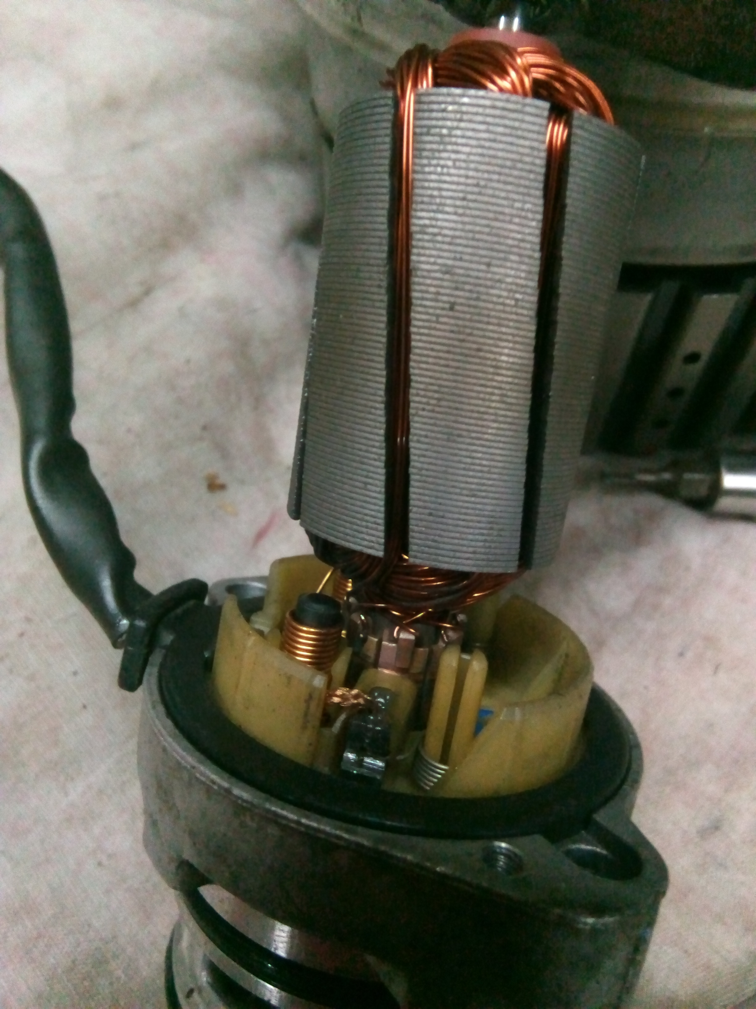
After a thorough cleaning and examination of my pump, I am getting 2.4 ohms at the connector and 6.2 ohms across the brushes. The brushes seem in good condition with little wear. Signs of wear on the armiture, but nothing too severe ( IMHO ). The pump seems to run well when connected directly to a 12v battery ( though not under any load ).

Does this sound right? I have little experience with dc motors and resistance. The wire from the housing to the connector is about 250mm long and aprox 0.8mm gauge wire.

Its a pain to get the haldex off, so I do not want to put it back together and refit to find I have a failed pump ( which is pretty common by all accounts due to the Haldex being a non servicable item according to JLR and can lead to drivetrain problems including failed diffs! ).

The VAG group recommends servicing at different intervals,for different vehicles though the consensus seems to be new oil at 20k and new oil and filters at 40k .

The different generations of haldex fitted by different vehicle manufacturers are all produced by the same company, Haldex, but the haldex control module is configured differently depending on the application.

A new pump is circa ÂŁ240 and a new Haldex unit complete a staggering ÂŁ3500. Anyone have any opinions ( other than just buy a new pump for peice of mind, as things are a bit tight at the moment ! ).

Thanks in anticipation

Richard

I’m assuming it’s a fixed flux ferrite stator? I know nothing about the Haldex I’ve never worked on one, but if it is then you need to check the resistance as you turn the motor because it will change as the brushes come into contact with new segments on the com, each segment is connected to a different winding. You don’t however need to worry about the stator resistance.
If it’s a wound stator you need to check the resistance of that too, expect the stator field resistance to be higher than rotor by a good bit. It’s unlikely to be a wound stator on something so simple, I doubt they employ anything such as field weakening on a Haldex system!
Can you post pictures of the connections for me to look at? And if there is a rating plate that too.

Thanks for your reply, I will take some photos today and hopefully you can advise further
Cheers
Richard

Ok, Here are the pics
first a photo of the complete Haldex


The pump and motor are obviously not the originals, you can se a date of 2018 on the case. The car is 2010

The following pics are of the internals.

I have searched online for specifications of this motor. The company which produced it are Haldex, who were subsequently bought out by BorgWarner
Thanks in anticipation
Richard

Hmm, those motor brushes look quite far gone.

I would expect the braids to be at the end of the slot not half-way along.

New brushes might well cure the problem. Make sure they are put in the correct way so the shaped chamfer fits the commutator, same as the old ones when you take them out.

Good luck.

BorgWarner is a huge company who I would associate with Turbo manufacture, they where the first company to really introduce variable vane turbo charging to the masses, originally on petrol and diesel cars but it transpires that petrol engines get too hot for them to be reliable. That may have changed in the last ten years however.

That motor looks to be wound rotor wound stator with wound shunt windings in series with the field/stator. To test it you need to remove the brushes and test the rotor and stator independently. To test the rotor check between segments at 180 degrees to each other, you need to see a balanced resistance on each pair. You could test with the brushes in but it’s harder to get individual segments because they tend to overlap a touch to get better computation.

Do NOT be tempted to increase brush pressure, it’s massively tempting ind I see why, but the brush weight is as carefully determined in the factory as any other factor.

Brush length is a hard call, you need to know new length to judge it. They need to be long enough in the brush box to be stable, they should be free to float and not clogged with carbon dust, they also need to be genuine manufacturer. Burshes are carbon infused with copper, brass, hundreds of other materials. This dictates wear rate, friction on the com, arcing/computation, motor health ultimately. Yes any old brush will work and make most people feel like a hero, it won’t do you long term favours!

As Richard points out they look worn, posted whilst I was typing. If you pop one out post up some pictures of the brushes from a few angles.
Morganite are a fairly useful contact if you need custom brushes, they will analyse yours and copy them as new.

Hi Guys
Many thanks to you both for your time and expertise.
I have found a motor recon kit online, with replacement bushes, bearings and I think commutator.


I will measure my brushes against the replacement dimensions.
It will be next weekend before I will be able to do anything further on the pump.
I think it may well be that the soldering is the skill that elludes me in this venture. Whilst I can solder normal wires and have various kit for the job, I am not too sure about having the precission for this job.
i will of course keep this post updated.
thanks agin to you both

Don’t think I’d fancy changing the com if it wasn’t needed. Looks ok to me. The angle of the segments will be aligned exactly, likely on a key way, and if the replacement is even 1 degree out you’re looking at faster wear And lower output, it may be that the repair kit will be spot on, but you never know.

1 Like

Incidentally, what problems are you having with the system? Or is it a routine service?

Hi Richard, hope you are keeping well.
As MrBarry has said, what is the actual problem you are suffering from, and what makes you think the pump is faulty? You say the pump seems to run well with an external 12 volt supply. It looks like a permanent magnet stator so not much to go wrong there if it is. I don’t think you can measure the coil resistance at 180 degree, as mentioned above, as it looks like a seven segment commutator, but if you put the meter probes where the brushes would contact and check by rotating the rotor one segment at a time the readings should be about the same all the way round.
I see the kit you have ordered contains a new commutator. You are a braver man than I if you try and replace that and I’m an electronics engineer of forty years. Years ago I used to pollish the commutators on old car dynamos and starter motors with fine emery paper paper but not sure how much of a good idea it was.
Also, do you rearly need four wheel drive? I ask because a friend of mine had a Freelander 2 and the Haldex unit packed up and due to the cost the garage she took it to dissabled the unit so it was just front wheel drive. As she wasn’t a off road enthusiast she noticed no difference except the fuel consumption seemed to go down a bit.
Good luck.
Dave.
PS your mk1 is still going great.

Carborundum stones. Now that takes me back a few years. Used to polish the down shop motor slip rings on one of our cranes quite regular. Think it’s a banned substance now??

I have only recently bought the car to replace my Freelander 1. It is a 2010 high miler at 150k, so was performing the 10 year (150k) service. Quite an involved job, cambelt and waterpump and all fluids and filters. Not for the faint harted as the rear diff, haldex and front power transfer unit do not even have an oil drain plug fitted. Remove and drain through the fill plug or extract as much as you can with a vaccum pump.
During my research I came across the resistance values for the pump quoted on the “haldexrepair” website, so thought I would check my pump whilst it was out to clean the filter.
There are many horror stories of rear differential failure on this model. Some have been reported after the haldex was serviced ( even though JLR do not specify any haldex maintance and do not list the filter as a service item ! ).
So I was just trying to dot the i’s and cross the t’s.
After reading all yours and others helpful advice, I decided to put it all back together today, with the existing pump as is, after a good clean. I did not fancy tackling the soldering even before I read your and Daves replies! defo not after lol.
Happy to say, after a short test drive off road, all seems well. No strange noises and I am defo getting 4 wheel drive.
I am going to take it for an extended drive this week and check for DTC’s and oil leaks afterwards.
Thanks agin for all your input
Richard

1 Like

Hi Dave, we are both well thanks, and hope you and yours are too! Happy the Eunos is still going strong and you are enjoying it.

I am “Mazdaless” at the moment, having sold both of mine to buy a Jaguar XKR convertable. Its a lovely car, but not as much fun as the MX5’s!

Thanks for all your input. You will get the gist of where I am at from my reply to Mrbarry.

We really do need the 4 wheel drive. We live in a remote part of Central France, and have 20 acres of land, horses, trailers, and a lake which is accessed from a long rutted track, which can be dodgy in the winter…nevermind the snow lol

Have a great Christmas. I will update this post if there is anything to report in the comming weeks.

Cheers

Richard