Hi all,
I wanted to do a brief summary of how I added OEM remote locking & boot release to my NB. It took months of research and sourcing parts because it seems very few people have attempted it or at least succeeded, so hopefully this will help out anyone who was in my situation several months ago and save you a lot of time!
Firstly, I want to thank MakerGeek Dan on YouTube for his very helpful video tutorial (I strongly recommend checking it out to help you get a better grasp on everything) and I want to thank Roadster_Robbie on here for his help with the alarm issue I was having (more on that later).
One final word before I get into it: This is how I did it for my specific car (Mk2.5 1.8). I can’t say for sure that the process will be identical for everyone. My car also came with full central locking (ie, a door lock actuator in both doors). If you don’t have this already, you’ll need to look into adding an extra actuator to your driver’s side door.
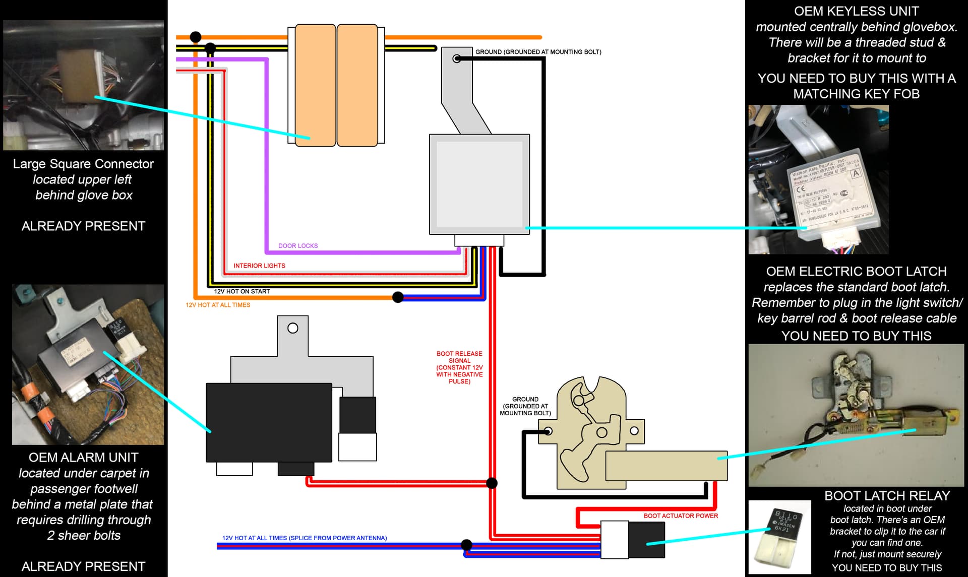
Lets start with the overall diagram I drew up. Then I’ll explain the elements:
You’ll need to acquire a few things as stated;
-
OEM Keyless Unit & Matching Key Fob.
You can find these on eBay for around £50. If you can, try and find one which has the 16 pin connector attached because they’re almost impossible to find on their own and it will save you the trouble of figuring out which wire goes where. The car will have a place for it to mount already there (remove glove box and look up under the dash, it should be right in the center. -
OEM Electric Boot Latch.
You can find these on eBay for around £10-15. These are a drop in replacement for the standard non-electric boot latch. The microswitch in the latch mechanism controls the lights and tells the car if the boot is open, it will plug in where the old one was plugged in. The boot release cable will attach in the same way as the old one as will the metal rod which links the latch to the adjacent key barrel. You may need to bend this rod slightly to get it to sit right and clear everything. The trim panel inside the boot is already shaped to fit the electric boot latch, so no worries there. -
B110 12V Imasen Boot Latch Relay
Again, eBay is the place to go for these. I’ve seen them for £5-10. I was fortunate enough to get one of these included with part of the loom when I bought my boot latch. If you can’t do the same, you’ll need to acquire the connector which the relay sits in as well as figure out a way to securely mount it (the OEM connector has a mounting bracket that snaps into a hole under the boot latch).
You’ll of course need wires and soldering supplies, but you knew that already!
Now here’s how I did it:
REMOTE LOCKING:
Disconnect the battery. Always disconnect the battery before you play with wires.
Remove the glovebox and locate the large square connector from the diagram. It should be mounted to a bracket, but you can pop it off with a bit of wiggling to give you easier access. This large connector should have all the wires you need coming from the left side and you’ll notice that some of them don’t continue past that connector. My car had the orange and black/yellow wire continuing through the connector, but yours may only have the orange. Whatever the case, make a ‘Y’ connection on the wires that continue through the connector and you can cut any that stop at the connector and join right onto the end of them (don’t forget to slide your heat shrink on first!). As per the diagram, you want to connect the Constant 12V (orange), Switched 12V (black/yellow), Door Locks (purple) and Interior Lights (white/red) to your keyless unit.
My keyless unit came with the wires already attached to the connector and the power wire was blue/red, hence the diagram. You may also find wiring diagrams showing a blue/red wire for power. Doesn’t make any difference function wise, it just runs through a different 10A fuse. Connect to orange.
The keyless unit has a ground wire (black). You can ground this however you like, but I chose to make a loop around the mounting bolt for the keyless unit itself.
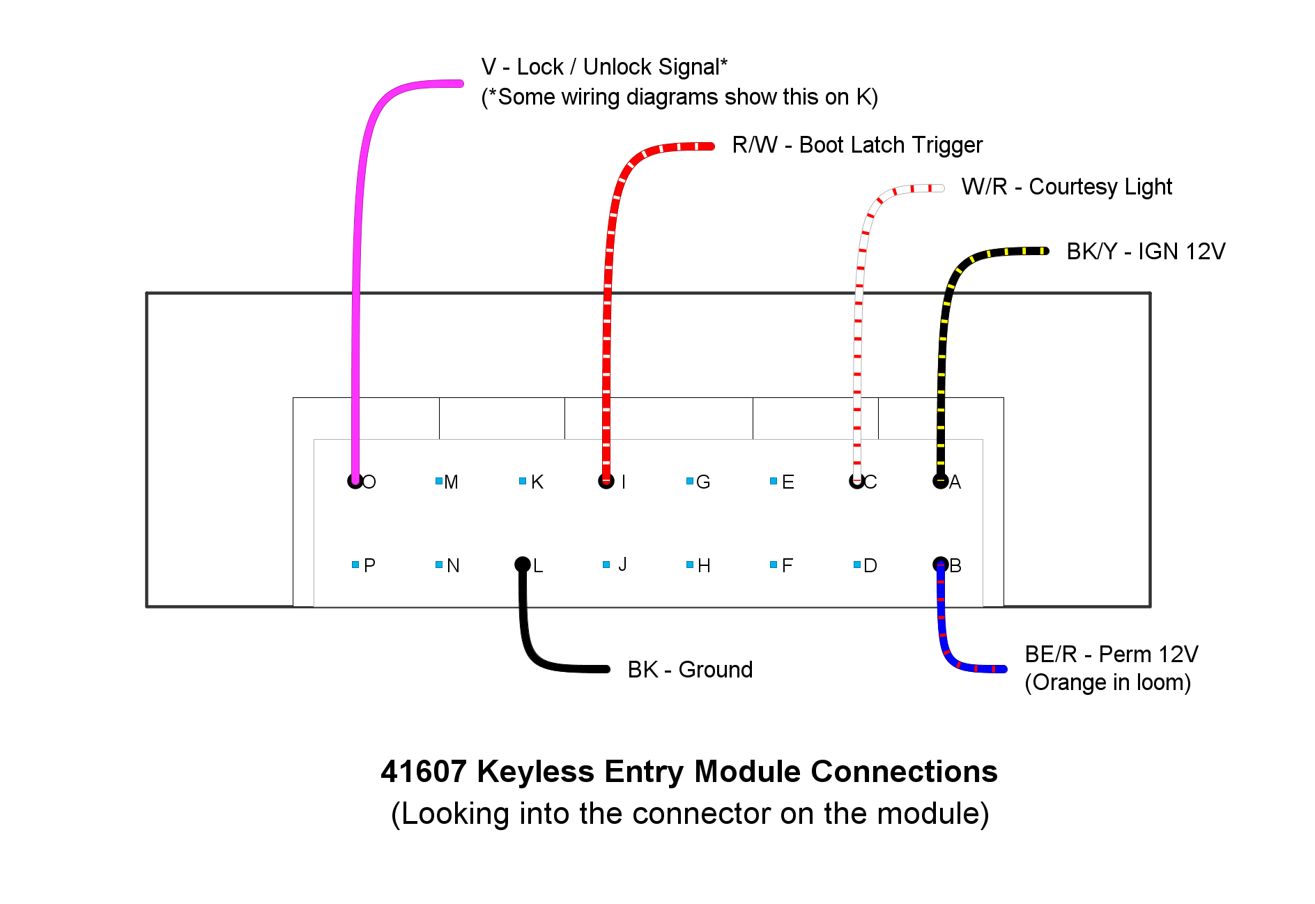
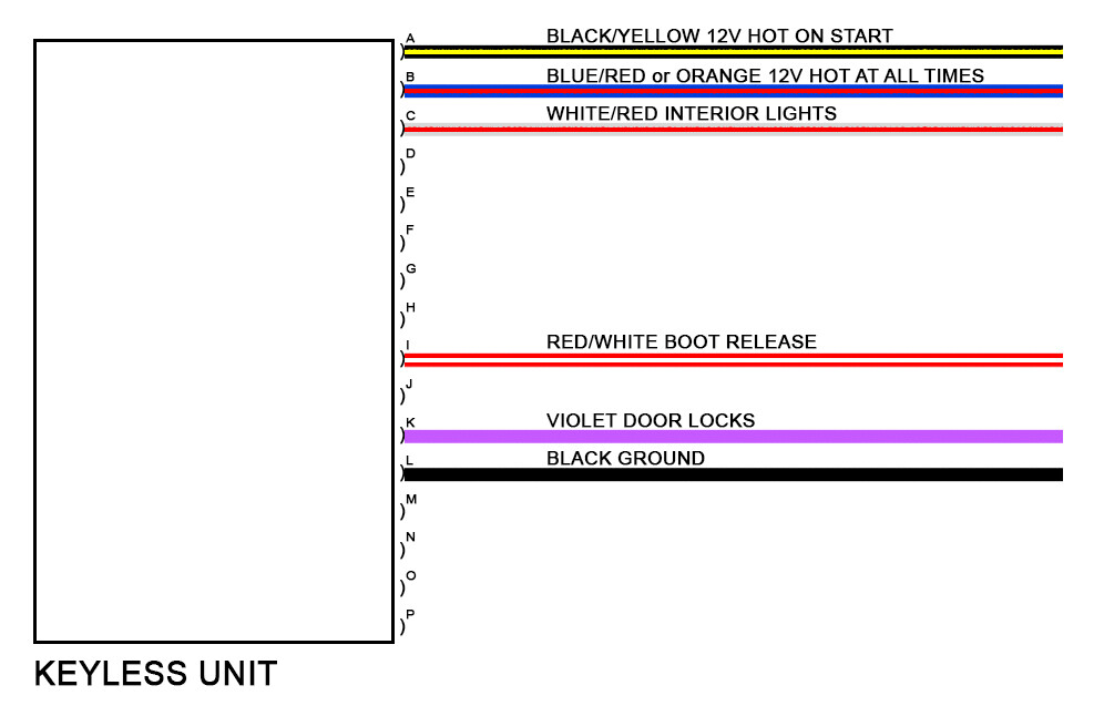
Here’s how the wires should connect to the keyless unit if you didn’t get one with the wires already present:
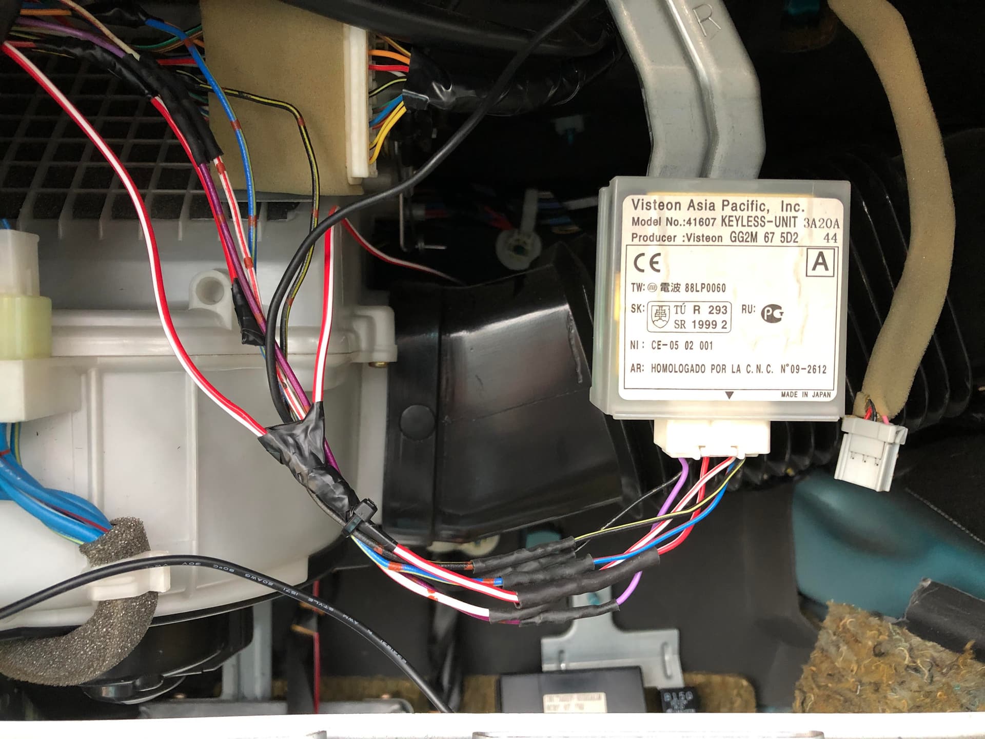
Here’s mine for reference:
PAIRING THE CAR TO THE FOB
At this point, you should have all the wires connected except the boot signal wire (red/white). Assuming your signal wire is taped up and secure, you can reconnect the battery and pair your car to your key fob. To pair your fob, you need to do the following procedure quite quickly otherwise it won’t pair.
-
Sit in the driver’s seat with the door open
-
Put the key in the ignition and turn it to the ‘ON’ position (not far enough to start the car) and then all the way off three times. ON, OFF, ON, OFF, ON, OFF.
-
Remove the key from the ignition
-
In the door jamb (down to your right) there is a little black switch, press this and release it three times.
If done correctly, the car’s locks should activate and the fob will now function. If you’re not interested in the boot release feature, you’re finished! Otherwise…
ELECTIC BOOT RELEASE
To add the boot release is a lot more involved unfortunately. I had a whale of time trying to splice into wires which were already present in the loom (how convenient) only to find out they had no continuity (how inconvenient) and so I ended up just running my own wires. Feel free to go probing with a multimeter and use the existing wires in the loom if you can.
Firstly, you’ll want to add the red/white boot latch wire to your keyless unit. It needs to be long enough to run along the sill and into the boot all the way to the latch.
I ended up removing all sorts of trim during this stage (most of which was unnecessary), so I’ll skip the steps of how to run a wire from the dash to the boot. There’s no right answer, just make sure you do it neatly and securely. Try to follow existing wiring loom paths if you can.
You also need to make ‘Y’ connection on this wire (I recommend doing it just after the keyless unit) and run that wire to the alarm unit. The alarm unit is under the carpet in the passenger footwell. To get to it you need to peel back the carpet (which requires removing some trim pieces and weather stripping) and you’ll see a metal plate held on with a bolt, 2 nuts and 2 big rivet-looking things. You’ll need to drill these out to remove the metal plate (argh), but fortunately there are 2 threaded studs just inboard from these which you can throw some nuts on when you put it back.
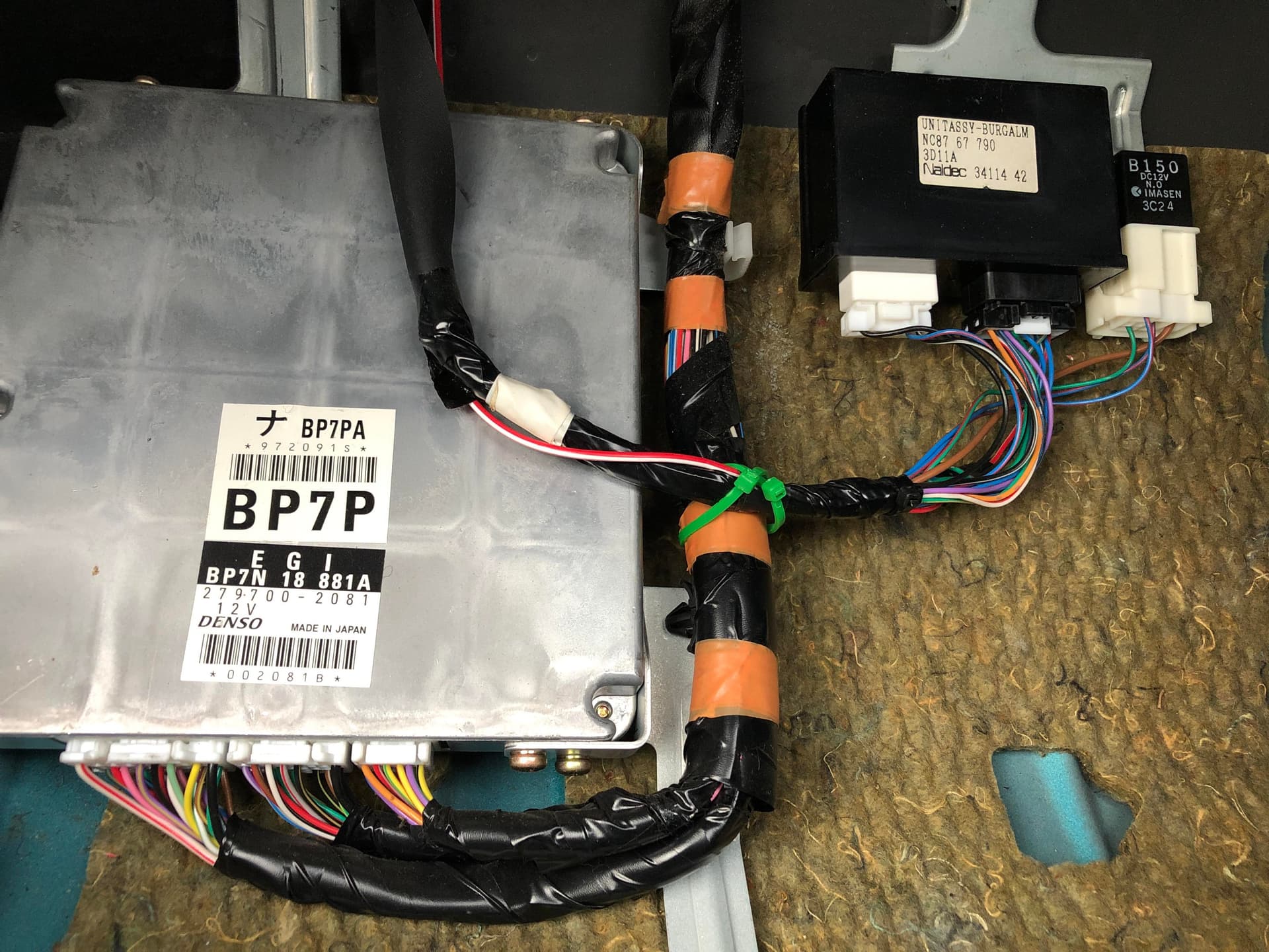
Under the metal plate is the main ECU and the alarm unit. You should find a red/white wire is already present in the bottom right corner of the middle connector, just splice your red/white wire into this one. There are no wiring diagrams for this because it’s an anti-theft device, so this image is as good as it’s going to get:
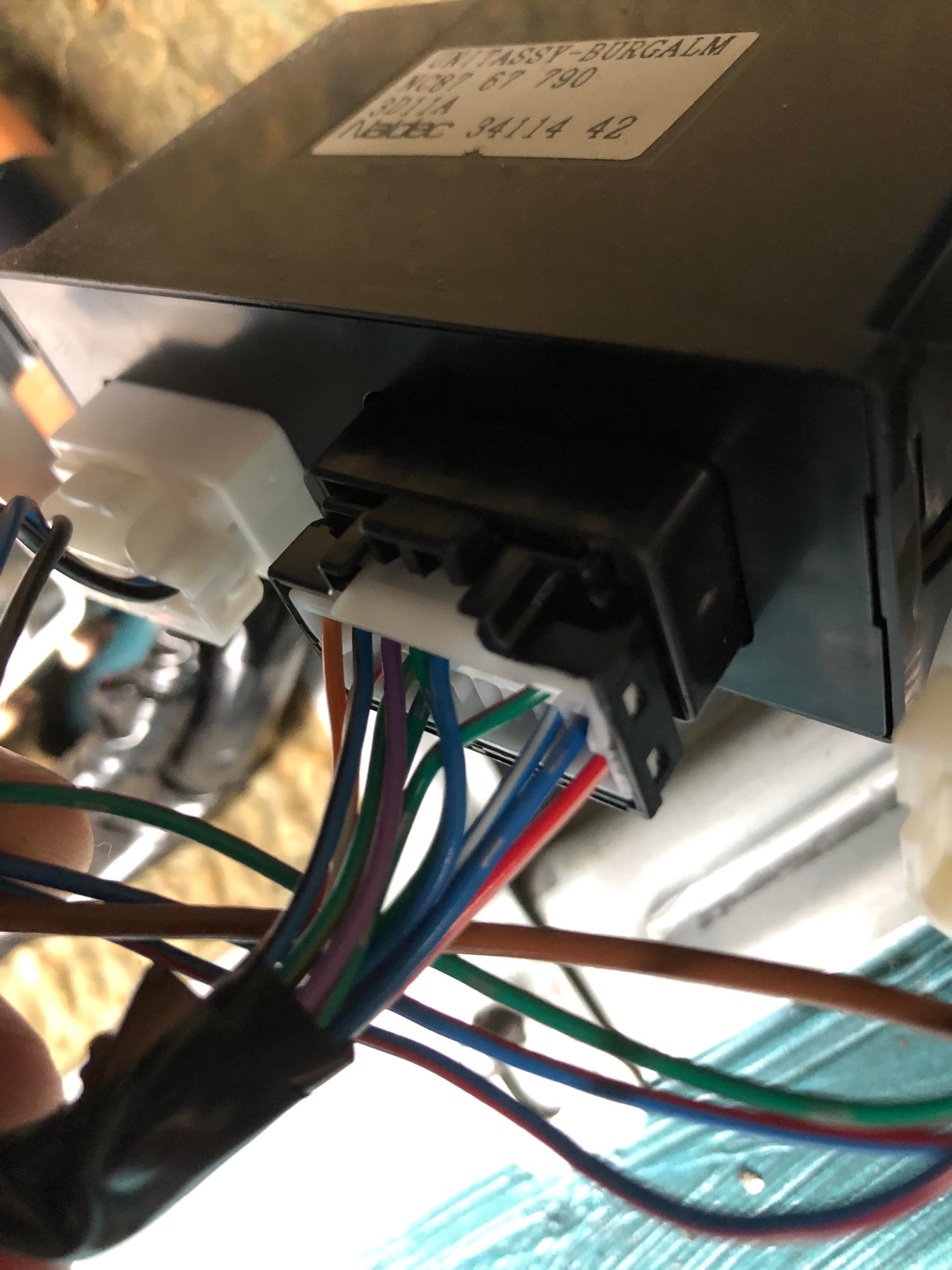
Here’s mine:
I ran the red/white wire along the existing loom into the bottom of the dash and then directly to the keyless unit (you can see the ‘Y’ connection in the image of the keyless unit).
This one caused a headache for me, because if you don’t run this wire to the alarm unit, the alarm will trigger every time you open the boot from the fob with the doors locked. Not ideal, but live-with-able for some who don’t want to pull the carpet and drill out the bolts. You just have to remember to unlock the car before you pop the boot. So again, massive thanks to Roadster_Robbie for the help on that one!
Now we’ll move to the boot.
As I mentioned, I was fortunate enough to find a latch with the relay and subsequent connectors already attached. If you aren’t as lucky, you’ll end up with a connector going to nothing with a red and a black wire in it. This is a ground (black) which I grounded to one of the latch mounting bolts and a power wire (red) which goes into the boot latch relay. Your red/white signal wire also goes into this relay and the other 2 slots are taken up by 12V power. I ran mine from the same power source as the power antenna since it was already in the boot, but you can run it direct from the battery if you want. The power antenna’s 12V supply is hot at all times (which you need) and runs through a 10A fuse, so I’d recommend putting an inline 10A fuse if you go direct from the battery. The 12V power just needs to split into 2 and fill up the remaining slots on the relay. Obviously, you’ll need to pin your own connectors or figure out something else if you don’t have the connectors with your boot latch.
Here’s the diagram:
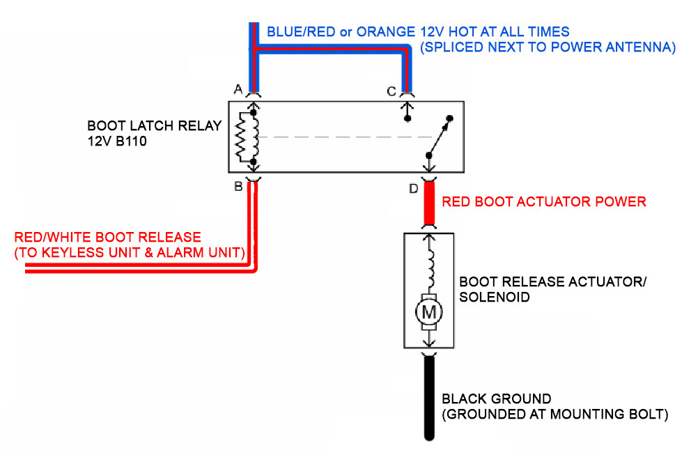
Once wired up, you should now be able to use your boot release button on the fob.
That should be everything. You should now have fully functioning OEM remote locking with remote boot release!
Hopefully this helps those of you who are in the process or are thinking about doing it.
Cheers!