I’m looking for technical help or recommendations on: __Diagnosing lights problem
Following re-connecting the battery terminals in the wrong order (neg first), I have the following problem:
A: Stalk in dipped position and switch rotated to first click (Sidelights and instruments):
Nothing lit up, and with the engine running, rapid clicking of indicator relay, but no indicators either with dash hazard switch or stalk.
B: Switch rotated to second click, headlights only on, but stay retracted, no side or instrument lights, and indicators as above.
C: Stalk to main beam position, everything works normally, headlights raise, sidelights are on, dim/dip works, indicators normal, hazard switch normal.
I’ve tested the stalk switch unit as described in the Grainger manual, and it’s OK, all the fuses are OK, and if any of the relays were naff, I assume condition C wouldn’t work. I’ve checked as many earths as I could find.
Rapidly approaching the end of my wits, so any help would be appreciated.
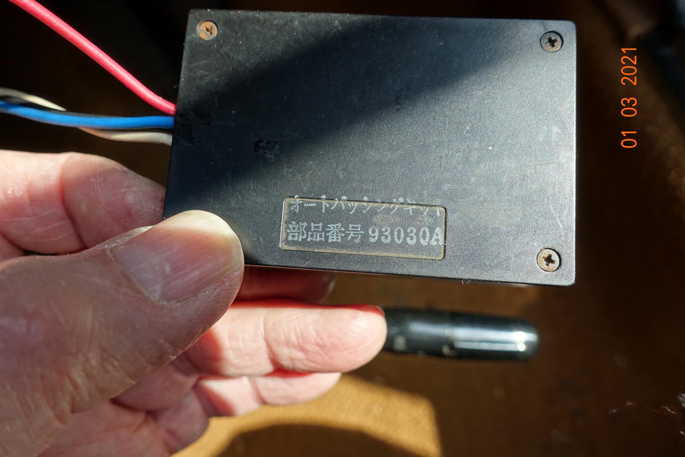
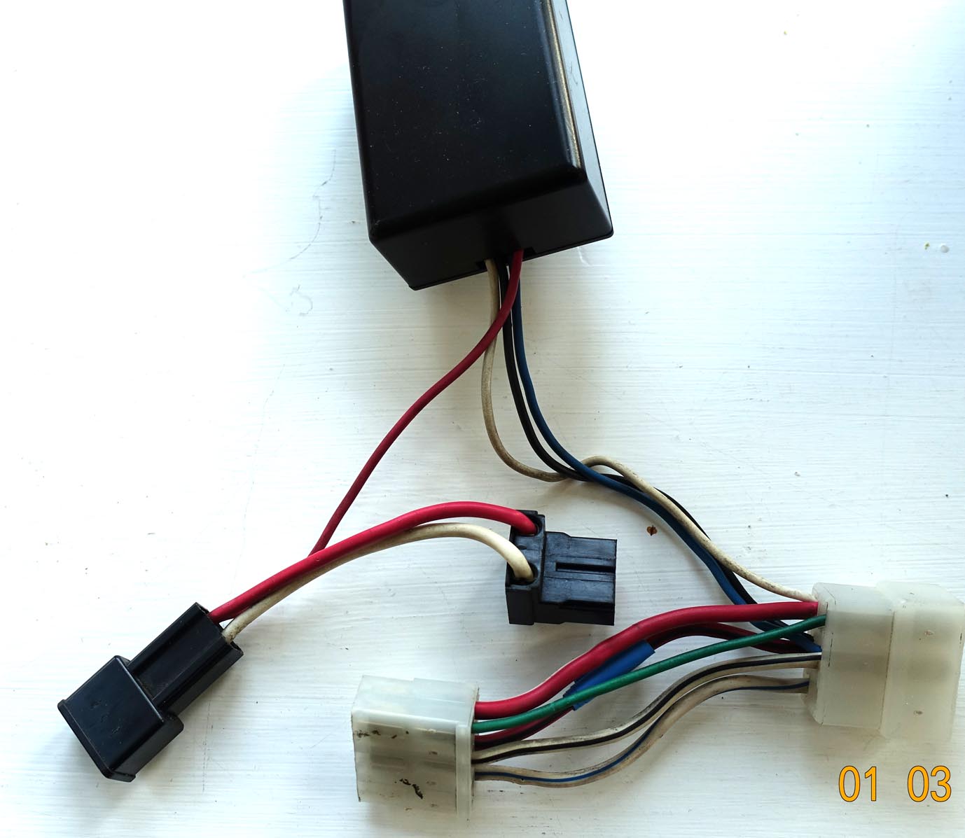
I’ve attached a photo of a “black box” that’s connected between the switch block and the loom…without this fitted, nothing works. I’ve looked inside and there is a relay, two diodes, a resistor, and a capacitor. These all test OK…but I have no idea what they’re function is.
Connecting the battery in the wrong order shouldn’t have caused any problems as long as you didn’t do in reverse polarity. Any other back story?
That extra box is odd. Has the vehicle harness got a grey and a red/yellow wire going to the plug? I think the 2 wires should be joined by what’s called a short connector by design. Hard one to call but I’d want to remove the box from the equation but shorting wires is a dangerous game!
Have you removed the short cord with the white 6 pin connectors on it between the combination switch and the original vehicle harness and plugged the main harness straight into the combination switch?
Hi,
Thanks for your reply…yes, with the “magic box” taken out of the loom, there’s nothing working at all.
As for the wiring colour codes, I haven’t yet managed to find a wiring diagram that matches exactly, despite spending hours trawling the web. (The car is a '91 V-spec, which I bought from the importer in 2002.)
The mystery is compounded by the fact that everything works when the headlamps are on main beam.
I would guess on the black box being an over complicated flash to pass mod. On the early Eunos pulling the stalk flashed main beam but didn’t raise the headlights.
I would guess that somewhere a fuse has blown or a main feed has failed which should provide power to all the functions that aren’t working. However when the main beam is on this flash to pass module is providing power to raise the headlights. This power is then feeding back to all the other functions causing them to operate correctly.
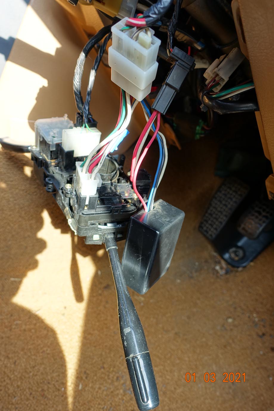
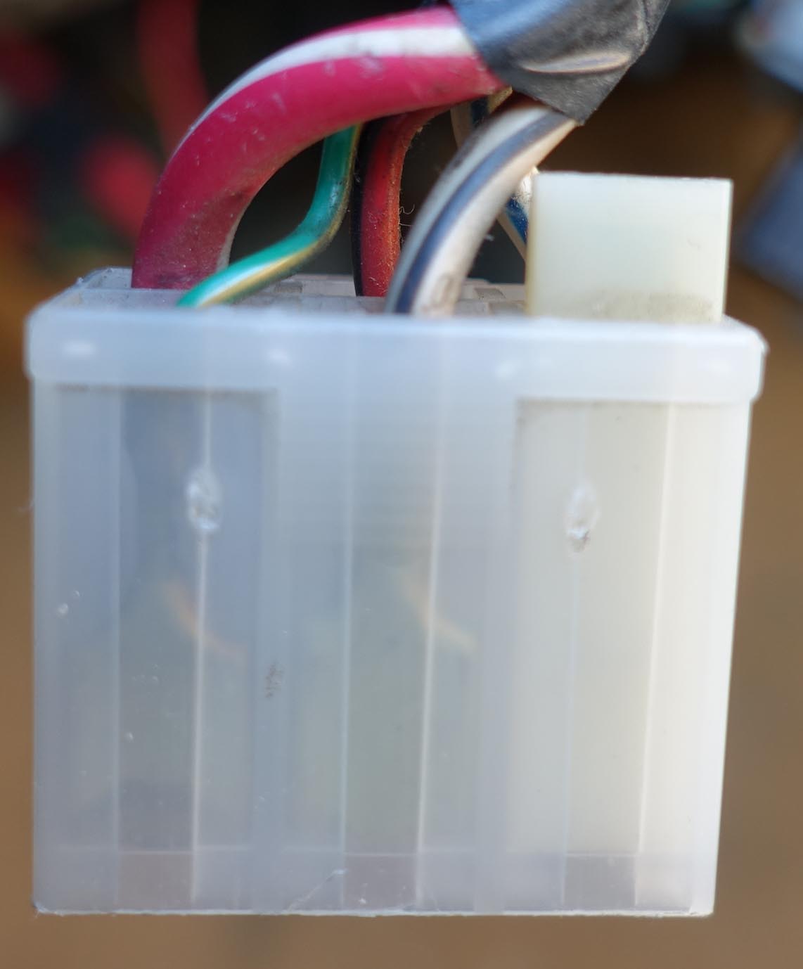
Thanks for that…it’s the first clue I’ve had as to the function of the black box. Here are some more pics. The first is the socket on the wiring harness. The colours on this match the leads on the black box.
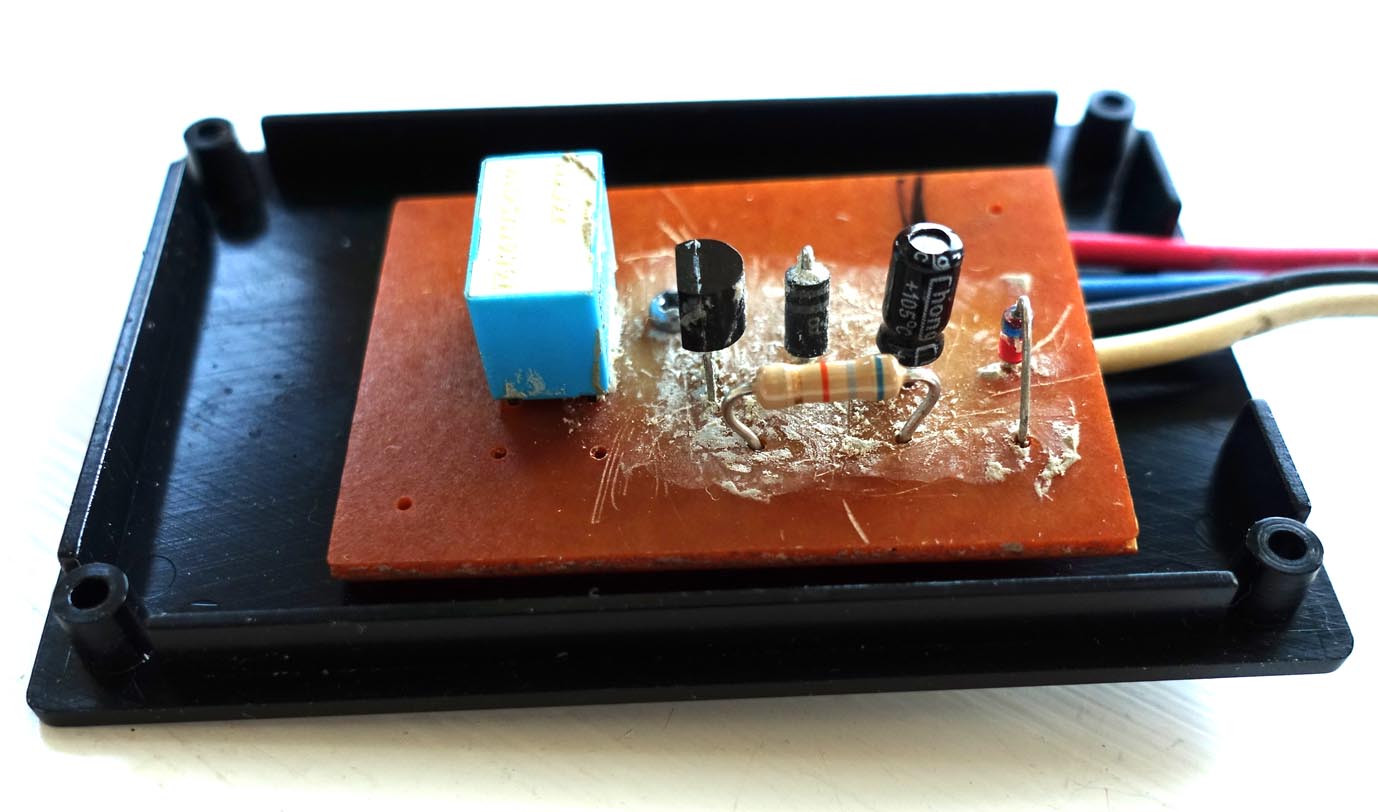
The box components were all embedded in a stiff putty like material which I had to remove. (I’d forgotten there was a transistor as well…) I replaced the resistor and the leaking capacitor. The diodes and the transistor tested OK.
I had a funny feeling I’d seen that box before. We have one on our '90 Eunos / Exocet to. I had to repair a wire in on it as it had ‘dangled’ loose and broken. We don’t have flash to pass so I don’t think its related to that.
This is what I can tell you about the wiring (from my UK wiring diagram).
2 Pin plug
Red/Blue wire 12V permanent live - White/Red wire 12V permanent live
6 pin plug
White/Black wire 12V to rear fog lamp with side lamps on (not fitted to Eunos so not sure what it’ll do on yours)
White/Blue wire 12V to tail lights illumination lights etc with side lamps on
Red/White wire 12V feed to main beam
Red/Black wire 12V feed to dipped beam
Green/Orange wire, not shown on this diagram I suspect maybe to do with front fog lamp circuit, not fitted to UK cars.
No rain today and a couple of hours to spare, so back to the problem…and I’ve finally sorted it.
The “module” that was interposed between the switch and the loom was apparently a factory bodge to enable the headlamp flasher to raise the lights in addition to turning them on. The early cars didn’t do this, and the switch unit was probably a parts bin component from another model (Mazda 3?). I rebuilt it with a new transistor, capacitor, and resistor.
I then re-made every earth connection that I could find, and pulled and checked every fuse and relay…all OK, but still no joy.
As suggested by Robbie, I then measured the voltage on the two-pin connector to the switch unit and found it only had 12 volts on the red/blue wire, nothing on the white/red wire.
That led me back to the fuse box under the bonnet, and the diagram in the Haynes manual showed me my mistake! I’d put the 30amp headlamp fuse back in slot 5 instead of slot 4…!!!
All is now working, and many thanks for the assistance. My conclusion is that the problem was simply a rogue earth somewhere, compounded by a fumbling old git!
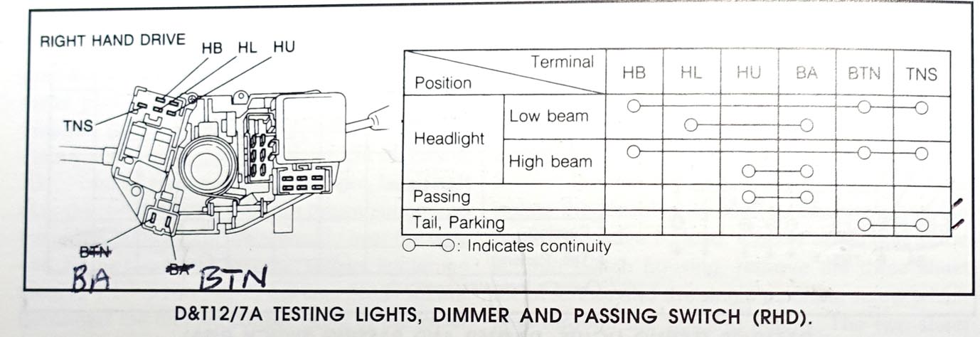
During this exercise, I discovered a typo in the Rod Grainger manual, and in the official Mazda manual that wasted a lot of my time, and led to me buying another used switch unit unnecessarily.
The terminals BTN and BA are reversed on the diagram. On the body of the switch unit, the legend is moulded in the plastic, very small and visible (to me) only with the aid of a magnifying glass. I’ve contacted Veloce publishing about this.
I find it hard to understand why they’d fit a switch that turns the headlamps on but doesn’t raise them…every mk1 I tried before buying mine had a fully working headlamp flasher.
My car also has a “one touch” drivers window which is not standard, afaik.
Don’t know about earlier Mk.1s but both my 1993 built “Series 1” 1.8 Roadsters have had drivers windows with one-touch overpress on the switch. (Actually, it took me a while to realise that it was an overpress and that there was also a first detent where the window would stop if I let go.)
Standard on Roadsters from July 1991. You can tell if a car has been retrofitted with the later switch, by lifting the console and checking how its hooked up. Early switches (and all UK Mk1) have a long tail on the loom, but the later switch has a short tail. So an early car with a later switch needs some wiring whatchmacallit.
I added a Wolf Miata window closing kit, and now have one touch up and down on both windows.
Post 1995 cars had a slightly different switch (same style, but the pcb is exposed) which seems to offer more reliable one touch.
“Flash to pass” only a requirement in the UK. Many Roadsters retrofitted with a little diode mod fitted when in the UK; not a MOT requirement, but people like it.
The simple mod uses a single diode with the negative connected to the main beam wiring (HU) and positive to the raise wire (HB). As soon as the stalk is pulled the headlight raises. Release the stalk and the headlight immediately drops. Simple and effective. The only shortcoming is that if you do a number of short flashes the lights will be bouncing up and down.
Looking at the components in the magic box shown above I would guess that the capacitor in the circuit is there to hold charge for a few seconds. This will keep the headlights raised for a number of flashes and the headlights will only drop back a few seconds after the stalk is released.

 !!!
!!!