Powered antenna on a 93 Eunos

Don’t read this unless you understand electrics - please, it’s confusing if you aren’t!

Faced today with a conundrum. I was trying to fit a powered antenna from a 93 Eunis into a 97 Harvard,* but it has four wires on the harness connection, Wire colours are Red/black: Yellow/black: Green/yellow and Blue/black.

Checked with ohm meter, no reading between red/black and any of the other three. About 25 ohms between yellow/black and Blue/black, and the same between green/yellow and blue/black. If I read between yellow/black and green/yellow it s about 11 ohms. (all figures are + 0.5 ohms roughly.)

I’ll be honest, when I heard the antenna had four wires, I figured a problem was on it’s way, My car antenna is a three wire connection, e.g. Up live, down live and negative (ground)

Now, no reading between red/black and the other three - fair enough, as the antenna is retracted (down) then I would assume that wire is the down connection, and the bottom limit has cut the connection. But. while I assumed the two wires reading about 25 ohms relative to the blue/black must make that wire a negative connection, but this doesn’t explain why I get a reading between the yellow/black and green yellow which is roughly half the resistance of either  to blue/black then WTF?

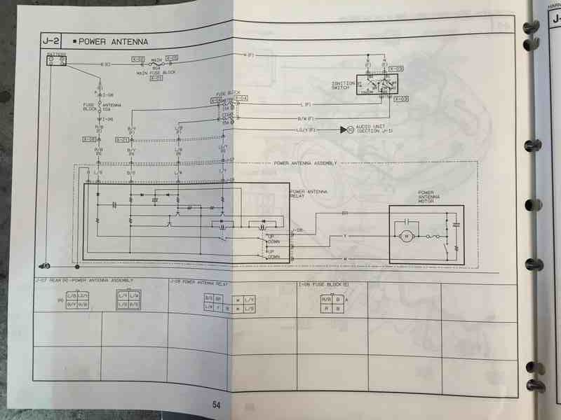
Anyone out there familiar with a four wire antenna, and any relationship to the animal I’ve tried to fit? There’s no name on it, so can’t source a supplier, but as it appears to be an OEM fit (Mazda harness and connectors) and on a Eunos, maybe someone out there knows the answer?

My current presumption is four wires mean a reverse connection to a DC motor, e.g. one pair is Pos and Neg for  rotation (up) and the second pair is the reverse of that - Neg and pos. This means it needs a reversing relay, which isn’t apparently present on the animal I tried to connect. However, a reading between the two wires as mentioned above puts that presumption in doubt.

So - in short, I’m up the swanee without a solution - unless someone has one.

  • NOTE - Mx5 parts say this can’t be done, they claim  up to 93 an early powered antenna can only be used within the range - 89 to 93. However, apart from the wiring, which should be surmountable if someone can explain what these four ways are meant to do, they also say mechanically it won’t fit, and it’s fitted.!

I’ll have a look at the wiring diagrams for you tomorrow evening GN. Can you confirm which wire colours are on the aerial and which are on the car harness.

Hi Gerryn

I have a 1997 MK1 1.6 that had the correct four wire connector in place. What does your three wire connector look like as makes no sense for the standard MK1 aerial. There is only one type and it has the four wire connector. I would guess that someone has remade the wiring in the past to fit a standard three wire aftermarket aerial. I can help if you require an original Mazda plug to connect to your Mazda aerial. 

Function is quite simple - the aerial earths through the mounting. The red wire with black stripe is permanent live. When the radio is turned on all four wires become live and the aerial extends and stops on limiter. When the radio is turned off the extra three lives stop being live and the aerial retracts. The wire colours should be the same on the car loom side too. 

I test all my MK1 aerials the same way with a harness. Rest metal mounting bracket on battery earth and all four wires on battery positive - this extends aerial. To retract you rest mounting bracket on battery earth again and just connect the red and black permanent live wire to battery positive.

PM me if you need anything.

Rob


See the Wiring diagram for the 1994 Miata.  It shows your four-wire Auto aerial with those colours.  It has relays and switches on the way to the motor, so the resistance readings are meaningless unless you take the lid off and look inside and find the right places to check.

Blk/Yel comes from the ‘Meter Fuse’ and is live during Run or Start, and goes to the ‘solid state’ module in the ‘power antenna relay’ inside the ‘power antenna assembly’ housing (Blk/Grn internally)

Blu/Blk comes from the ‘Cigar Fuse’ and is live during Acc or Run, and goes to the ‘solid state’ module in the ‘power antenna relay’ inside the ‘power antenna assembly’ housing (Blu/Wht internally)

LtGrn/Yel comes from the ‘Audio Unit’, and goes to the ‘solid state’ module in the ‘power antenna relay’ inside the ‘power antenna assembly’ inside the ‘power antenna assembly’ housing (Blu/Yel internally)

Red/Blk comes from the ‘Antenna fuse’  and is always live, and goes to the ‘power antenna relay’ inside the ‘power antenna assembly’ housing (Blu/Grn internally)

Ground return is the metal of the ‘power antenna assembly’ housing, not a separate wire. (Blk internally)

None of these external wires go direct to the ‘power antenna motor’.

The ‘power antenna motor’ has three internal wires from the ‘Power antenna relay’, Yel to the motor, the other two (Brn, Wht) to the limit switches and then the motor.

Good luck


 Edit.  I just had a look at the 1997 wiring, and it should be the same as the 1993, with the same four colours.  You might be looking at the three wires that should be coming out of the ‘power antenna relay’ and internally connected (as above) to the motor.


Rob - thanks for your reply, but I think you misunderstood me - it’s a four wire plug with four wires, colours as stated.

It came off a 93 NA Eunos  and hopefully I will wire in to a 97NA Harvard. The three wire plug I mentioned is on my car, which is an NB. (Mk2.5).Not convinced about the mounting being negative, if so - why three wires on my NB and four wires on the owners old Eunos? One of the three wires on mine is Ground, the other two are up and down - simple. As I said, I get a reading between two wires and a third, so the third must be negative, but then I get a lesser reading between the two wires, which is where theories go out the window. The fourth wire does not read between any of the other three.

While I didn’t try as you suggested, it makes no sense for four wires to be live at the same time, to me anyway. While I admit I could be looking at a non standard antenna, it still has a four pin connector that mates to the Eunos wiring, but that car is in zummerset and the owner was here with the Harvard, and one Eunos antenna. He’s non electric, so couldn’t make any pre-checks for me before cutting the harness wiring so I could re-use the plug. There’s no external wiring on the Harvard, just the two pole fuse/socket hanging in space. I’m going to do the rest, when I know what these B wires do!

O/K - I sat and thought about this and come to this conclusion - you could be right! That would explain why the red/black has no reading, as I thought - it’s the down wire for the motor. But, it. does need to be permanently connected as you said. Why it takes three wires to signal up is beyond me, but I’ve had a suspicion there’s a relay inside the box on the side of the unit which is not easily opened. Solution seems to be - suck it and see. I will -thanks.


Hi Gerryn

I am always playing with these aerials and I can fully understand why the MK1 version is confusing. It is a lot more complicated in operation than the MK2 aerial but from my experience much more rubust particularly where the mast in concerned but also with with regards to corrosion resistance. I can confirm that the battery test will always work on the MK1 aerial with no problem and AFAIK all the wiring should be present in the 1997 Harvard. As you say there is a connector with heavy black and red wires for the dual fused little fuse box. This is for the electric aerial and heated rear window. Before I fitted the bespoke little fuse box which actually attaches to the aerial, I just plugged fuses directly into the plug to good effect. The loom wiring is very complicated and the MK1 aerial has a relay builtin.

MK2 is totally different with three wires. Black is wired earth, blue with red stripe is permanent live and grey with black stripe is switched live. Testing is more fiddly but again do-able with a harness. Took me quite a while to work it out how to test the MK2 aerial and if you search there is a thread with the test I finally worked out for myself after asking on here first, not getting the answer and then publishing the answer for others.

I am still confused with what you are trying to achieve with the MK1 aerial and your MK2.5 - are you simply trying to test?

Whatever you want to do, It can be done. Not done it before but it should be very easy to wire the MK1 aerial into a MK2.5 and vice versa.        


Does this help Gerry?

Rob (Rhino99) Not trying to fit a Mk1 powered antenna to my Mk2.5, trying to fit it to a Harvard (Mk1) I drew comparison to my antenna as it’s different, and simpler electrically. You certainly helped give a clue, but we both need to thank Richard and Robbie for a detailed explanation - well done Guys! Many thanks to each.

Rob makes a comparison between the Mk1 and Mk2 antennas, their weatherproofing and construction which is interesting; but from an electricians POV the Mk1 four wire is a nightmare IMHO, there’s a simpler way to achieve up/down motion which I assume is present on the Mk2 antenna, while the Mk1 uses a very complicated circuit internally to achieve the end result.

From square 1 it was obvious to me that a relay was required internally to prevent reverse (down) operation while voltage was still present on the Up circuit, otherwise the antenna would stay in a switching state - going up and down alternately. (Great fun but totally undesirable!)

I’ve spent most of my working life (66 years!) working on relay circuits and electrical control, but it’s going to take me a while to figure out those internals on the Mk1, as simplicity defies complexity!

Ciao.

Gerry

O/K - the jobs not done yet, as the owner drives occasionally to Chesterfield and back in a week-end. So made up my mind what I’m going to do is this - connect all three ‘up’ wires together via a relay (on/off) and keep the red/black live all the time. One side of the relay coil is connected to live, and the same live connects to one of the switched poles. (it’s SP/ST throw relay) The live connection will be from the ANT fuse box in the boot. Running a negative wire from the new dash switch, right through to the relay, where it connects to the other relay coil connection. The new switch is DP/ST with led light indication, so it needs both neg and pos connections so the led works, but only one switched neg, where the outgoing wire to the relay connects.

Nearest pos and neg feeds are the radio, so going to link those to the switch. The aftermarket radio has no outgoing feed for a powered antenna.

This way is foolproof IMHO - the live feeds are ’ belt and/or braces’ from the original designer of the antenna, so connecting all together makes sense. Sticking the relay in at this point means there’s no possibility of the antenna going up, unless the switch and relay are on. As the radio feed is not live till the ignition switch is set to either ACC or IGN then the antenna can’t move. The live red/black will always bring the antenna down if the ignition switch is not set to either of those two conditions, antenna switch
on or off.The relay coil load and the led is marginal, as far as taking the pos and neg feed from the radio, so this shouldn’t place an ‘overload’ on the radio fuse - though as it’s the same rating (10 amp) as later models that have a powered antenna, then it’s adequate for them as well.

I posted this if anyone else has the same problem, so it’s there for anyone who needs it.

Footnote- SP/ST is single pole, single throw (on/off only) DP/ST thow is double pole, single throw ( two wire switching, on/off.)

If anyone doesn’t fully understand any of this - PM me.