The last couple of weeks I’ve been playing around with extractor fans, and their ducting.
One fan location in particular has been wearing out a succession of fans, whereas the other identical fan next to it has been fine for years.
The only difference between them is length and diameter of inlet duct and therefore its difference in pressure resistance.
So as usual I looked up the pressure drops for given airflows for the bend, the pipes, the grilles, etc and put them into a spreadsheet.
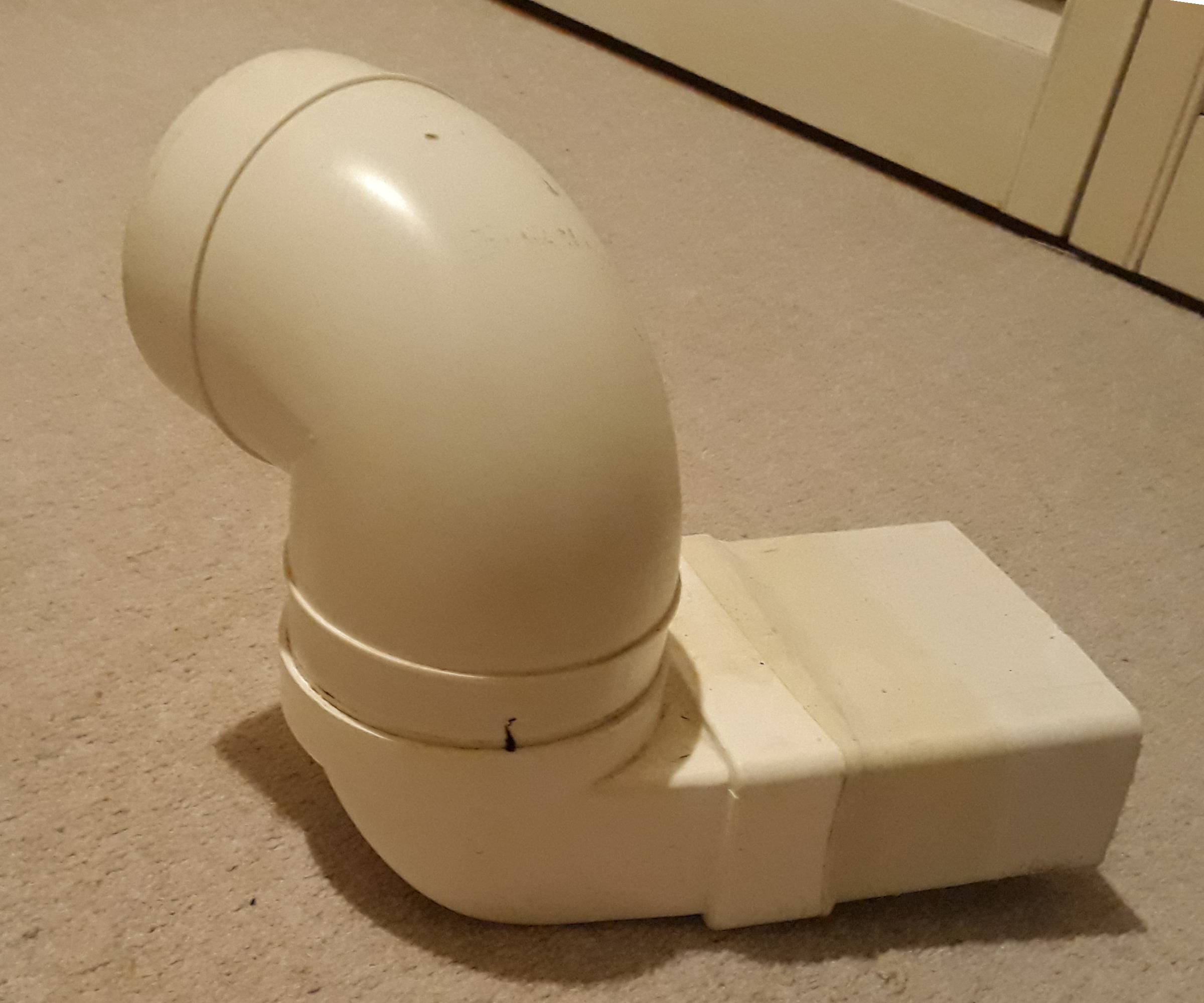
I took out two 90degree 100mm elbows, one of which was an adapter between 100mm round and 4" x 2" rectangular (necessary to get out of the loft past the eaves). These were replaced by two bends of half as much deflection ie 45 degree elbows and a smooth inline round to rectangular adaptor.
All my figures were from published data at a notional flow of 30litres/second.
Pressure drop in this section has improved from 63Pascals to 34Pascals.
Previous bits now removed
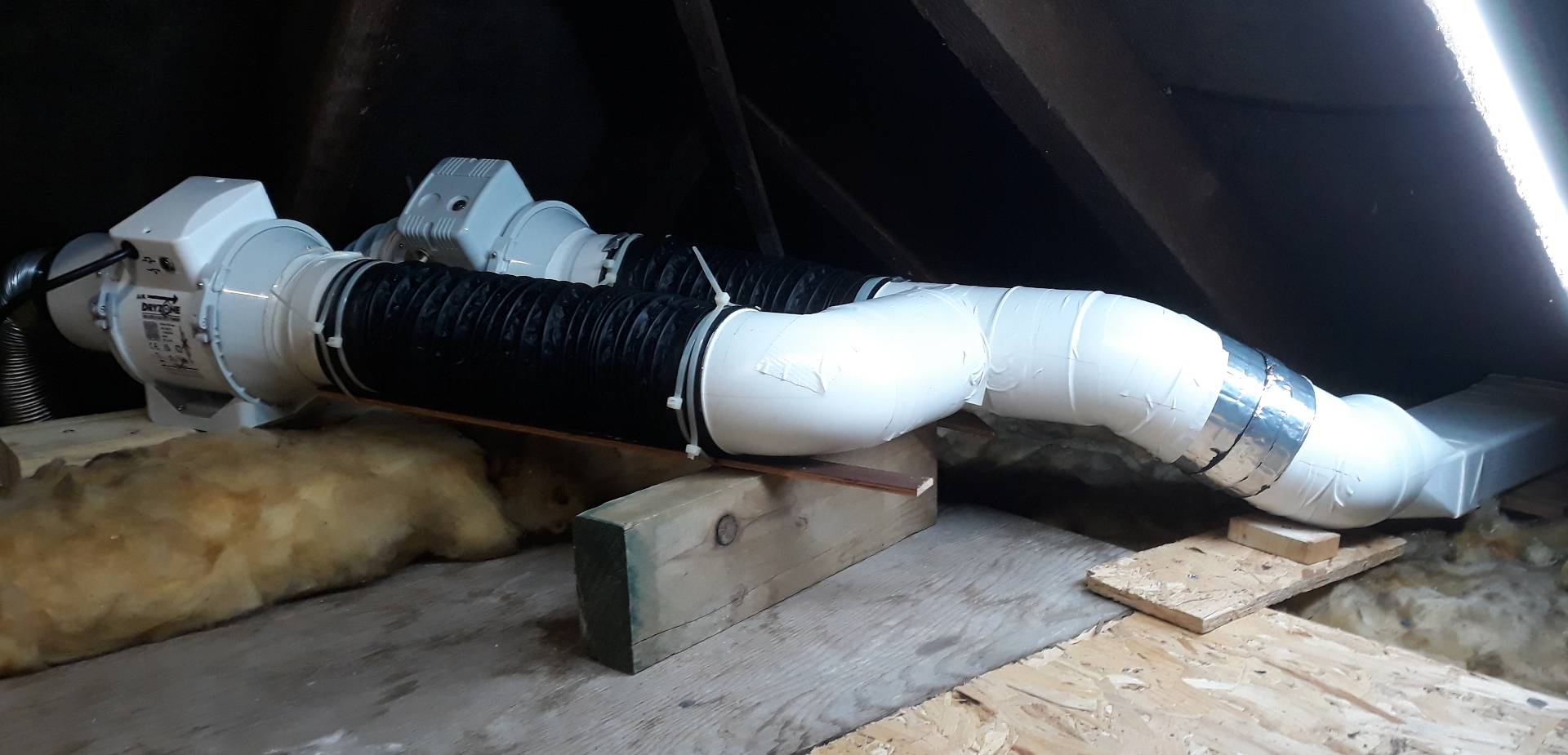
Replacement bits, less neat but smoother and half the resistance

This is the whole system in the loft so far, more work might happen…
The next most resistive part in the ducts is the anti-backdraft flap in each leg at 40Pa.
So why bother posting this? It has a direct bearing on Turbo and Supercharger piping.
Some simple and very obvious rules fall out from the maths:
- The bigger the pipe diameter the very much better; Flow volume = (Pi x radius^4 x pressure drop)/(8 x length x viscosity)
- Bends must be avoided or smoothed out; eg 90 elbow is 21.1Pa, 45 elbow is 8.2Pa
- The shorter the pipe the better.