Over the weekend I fitted the Nextbase hardwire kit for a Nextbase 512GW Dashcam. It was almost straightforward on the PRHT NC, and the few little niggles were easily solved with some patience and the correct tools.
The on-line 2008 MX5 Manual was very useful, especially to help with where the various clips are located for ease of dismantling. I recommend familiarising yourself with the layout behind the trims by reading the relevant bits and links found in kick panel trim, A-pillar trim and Header Trim before starting the job.
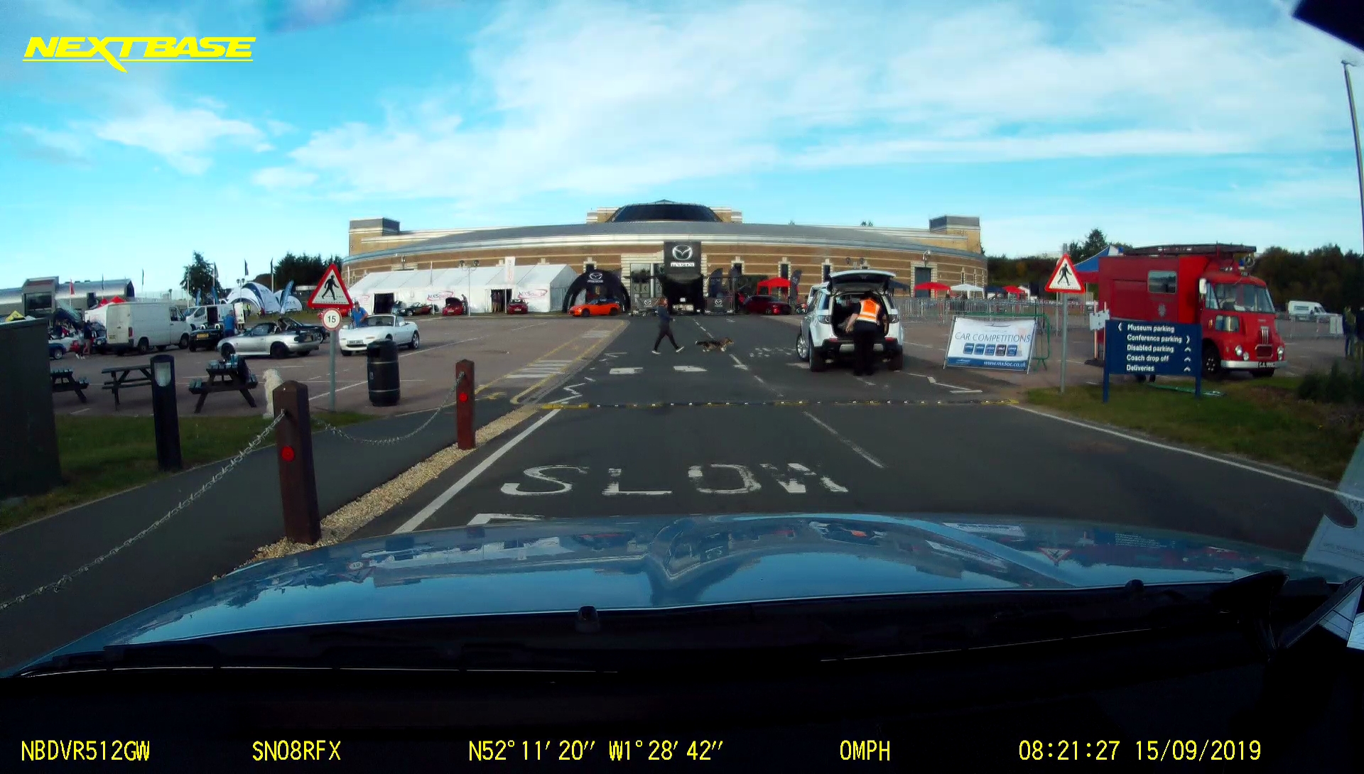
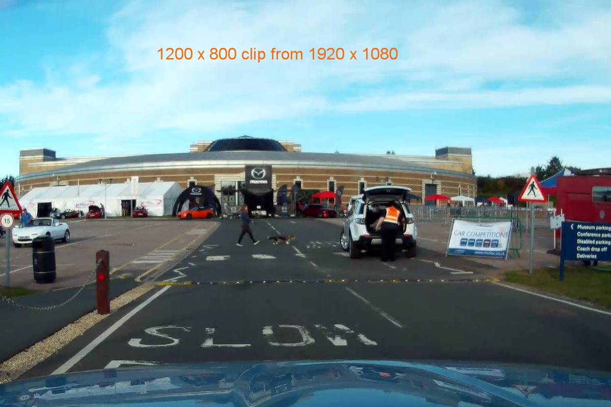
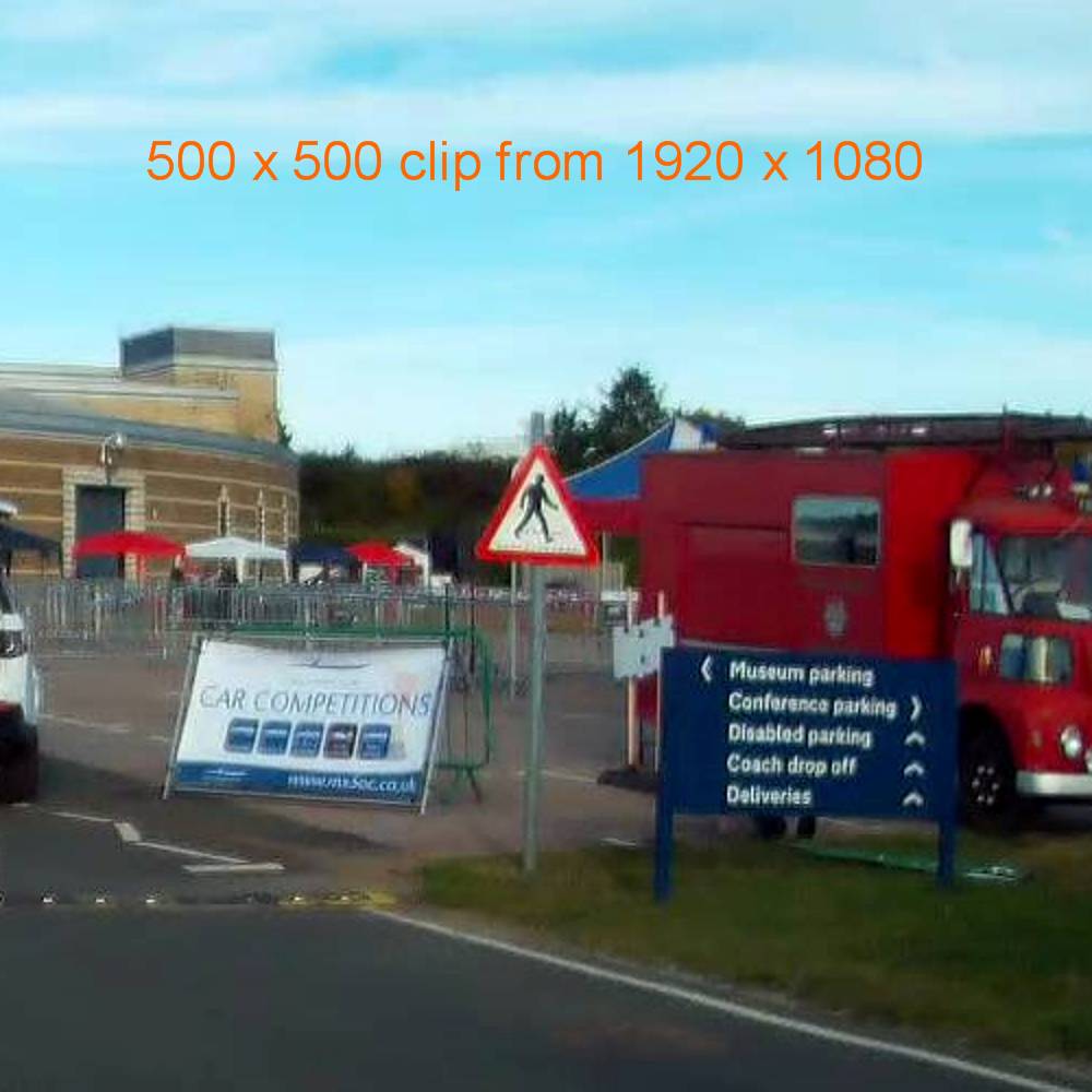
First of all, before any dismantling, I tested that the kit worked with the camera and did not interfere with the radio. As a bit of engineering overkill I added some ferrites to the leads in strategic places (both sides of the 5V converter, and near the dash-cam) to minimise any chances of extra noise on weak stations. Later I’ll add some screen shots off it from the drive to the National at Gaydon.
Preparation.
. Make sure the car is on level ground with enough room for easy access to the passenger foot-well. Open the roof.
. If you feel you are likely to short wires inadvertently, it might be wise to disconnect the ground terminal of the car battery. I didn’t bother, I have spare fuses.
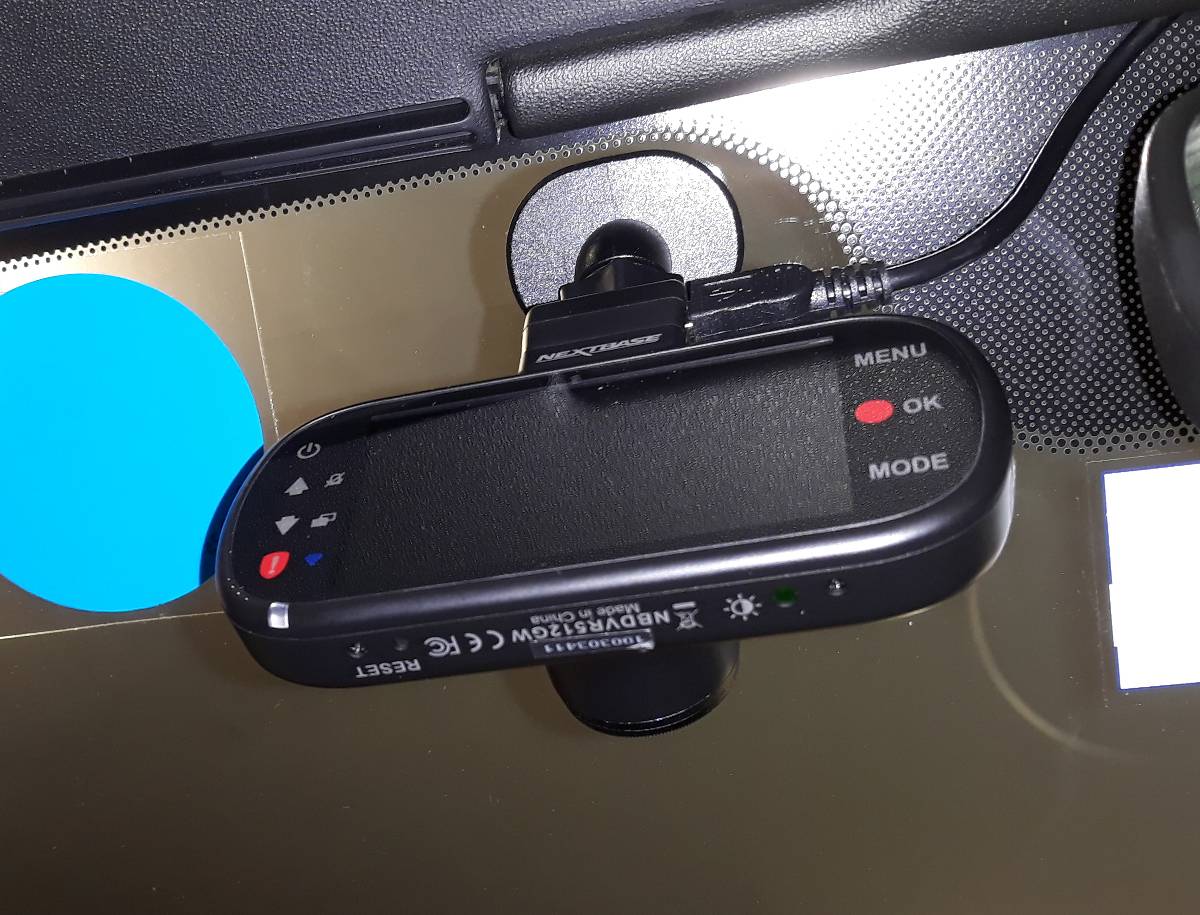
. Choose where the dash-cam will be, clear of sunshades and mirror adjustment and not in driver’s line of sight. Stick the permanent bit of the mount in place as a guide for later.
. Remove both the female landing wedges for the roof corners. The T40 Torx bolts in my NC were barely finger tight!
. Remove A-pillar trim on both sides; pull the top towards the centre of the dash and then lift it out.
. Removing the header trim is easier said than done. Here I needed to ignore Mellens regarding the map light, because the light was stuck in the trim by a bit of rubber and its lead is too short for removal anyway. Undo the two T30 Torx screws hidden by the sunshades. Pull down each end to release the clips. The fifth and final clip is in the centre beside the light, release this carefully so as not to strain the light’s lead and unplug that from the light.
. Remove the glove-box; unclip the damper cord, squeeze the cheeks to drop it forward, and lift away.
. Remove the left side sill scuff plate; ease out the inner sides at the front and back and lift. Sliding the seat forward makes releasing the back inner side very easy.
. Pull back the seaming welt now exposed.
. Remove the left front side trim (kick-plate); pull the centre-pin fastener, pull the front of the trim out into the foot-well, a trim tool will help to release the white clip by the fuse-box, and lift the trim clip off the sill seam.
There is now full access to the whole route for the hardwire kit cabling.
Installation.
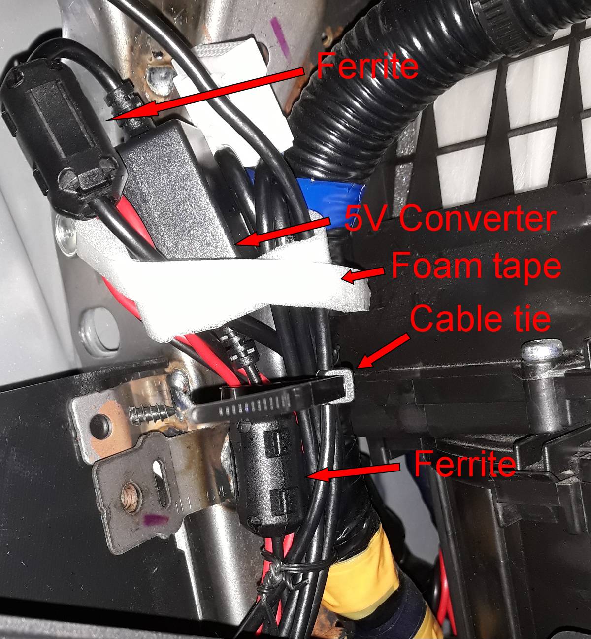
. Pass the dash-cam lead through the supplied ferrite two or three times, and gently clip it shut, leaving about 20cms free to the mini USB plug, enough to tidily reach the mount when the header trim is back in place. I also added a clip-on ferrite to the lead leaving the 5V converter box and another to the red and black twisted pair of wires entering the box.
. Notice in the header trim there is a convenient empty recess in front of where the map light lives. I chose this as the place for the bulky Nextbase ferrite, wrapped in some foam tape (draft excluder) to prevent it from rattling.
. Using a leather punch, I cut in the front edge of the header trim a small two-thirds hole the same size as the dash-cam lead, positioned about halfway between the end of the empty recess and the camera mount.
. Measure out the positioning of the new lead and the ferrite and heading trim to make sure of the fit to neatly reach the camera, and then cable tie the lead to the existing loom often enough to prevent rattles, all the way down below the upper surface of the dashboard. Keep the lead away from any sharp edges.
. There is a big empty space on the left above the inside fuse-box where the main cable trunk is visible, this is where I temporarily parked the converter box and the surplus leads before finally tidying them.
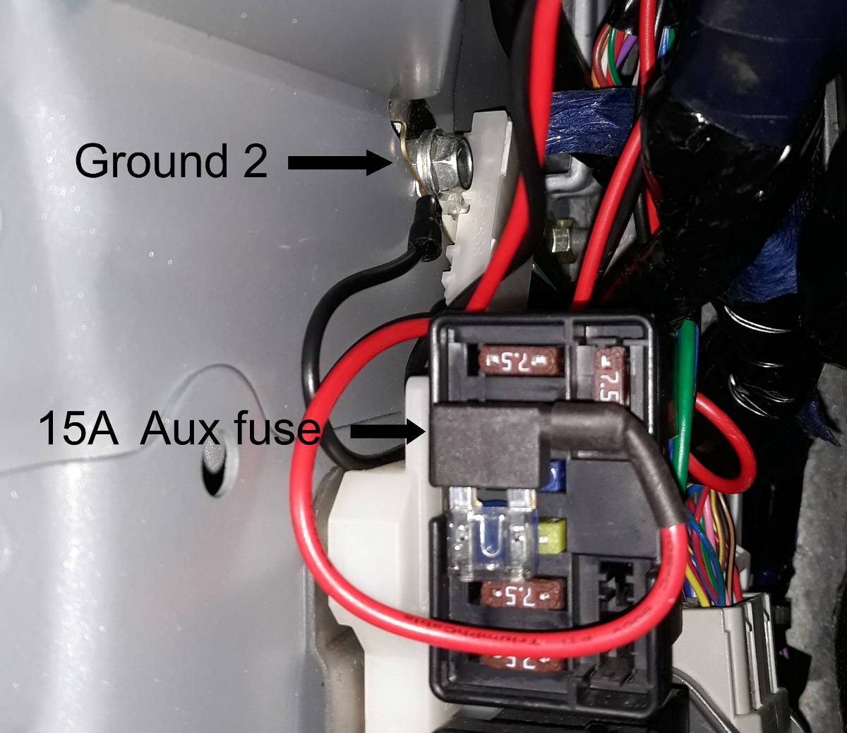
. Behind the fuse-box on the left behind the kick panel is the Left Ground G2. I used this for the black wire from the converter box, a 10mm ratchet ring spanner is the easy way to slacken and tighten the bolt.
. The red wire from the converter box goes to a 2Amp fuse in the piggyback fuse-holder in the 15A Aux Power fuse slot. Ignition Live is on the left side of this fuse so the red wire dresses awkwardly to keep the two fuses independent.
. Tuck the wires to the left of the fuse-box and above, tidy the bundle and converter with a cable tie and some foam tape to stop rattles, and finally secure the bundle to the big cable trunk.
. Check the camera works before covering up anything.
Closing off again.
. Refit the kick panel trim, making sure the clip is on the sill seam, and secure the fasteners. Check the new wiring is not fouling it anywhere or stressing the fuse-box.
. Refit the seaming welt.
. Refit the scuff plate.
. Refit the header trim WITH SUNSHADES DOWN (to avoid breaking the mirrors), making sure to re-connect the light plug and locate the new big ferrite in the convenient space, and dress the new lead out through the small slot. Secure the two T30 bolts.
. Check the camera works again.
. Refit the A-pillar trims
. Refit the female wedges loosely, leaving the T40 bolts only just finger tight. Close the roof and lock the centre catch. The wedges should have self aligned, and the bolts can be tightened to the correct torque (9 – 14Nm).
. Check the roof opens and closes smoothly, paying attention to the wedges.
. Tidy up all those trimmed ends from the cable-ties and vacuum etc.
Pictures updated 26/04/2020 with direct image instead of via imgur
Links to NC manual updated 26/12/2020 because Mellens is NLA.