Can I have advice on wiring up switchback DRL’s into my 2009 NC please.
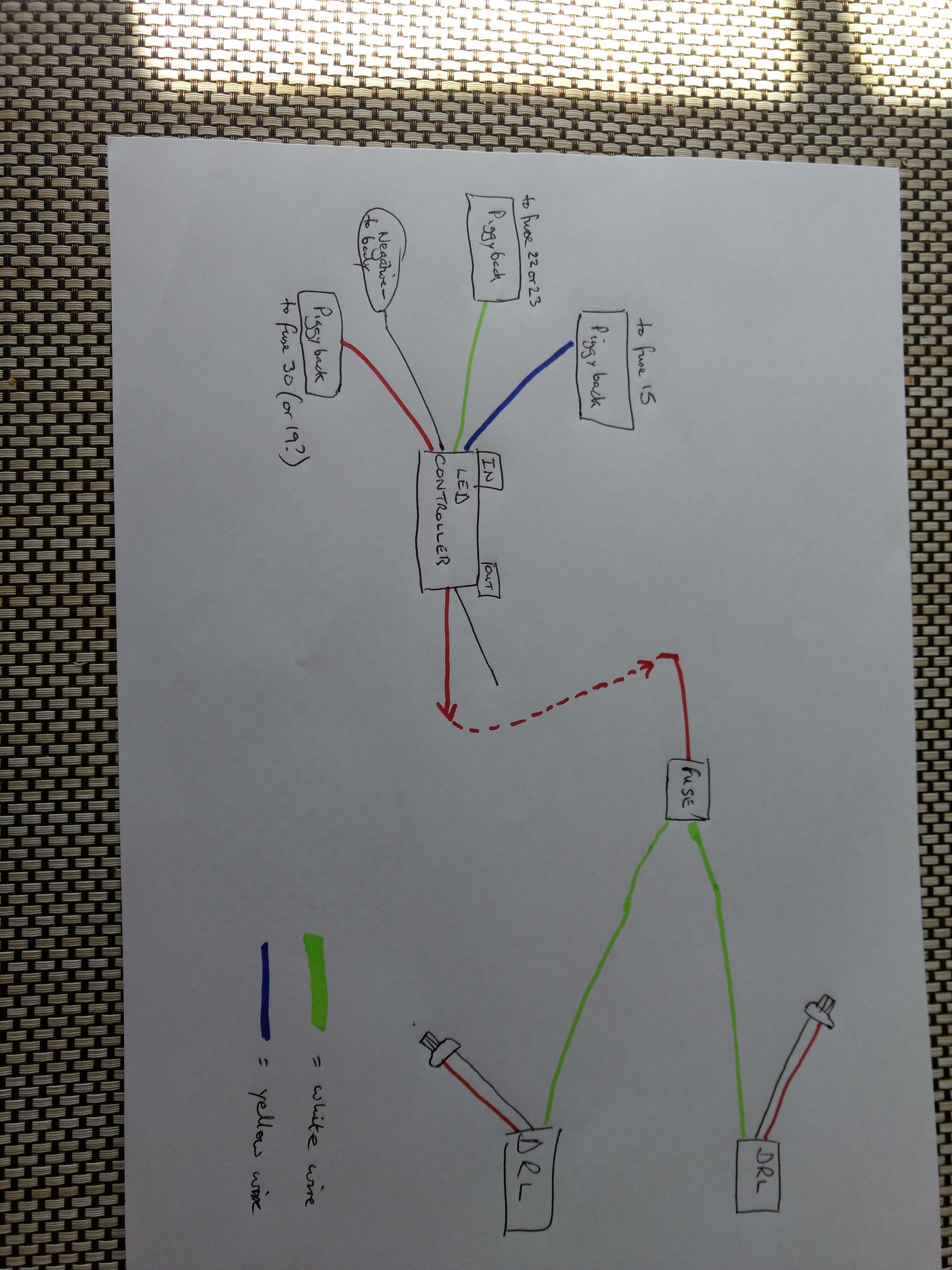
I’ve prepared a simple wiring diagram of what I understand the connections should be. I am using one of the LED Controllers (I know they can fail, so may end up using a 5 pin relay instead).
I think the black out from the controller should go to the negative side of the DRL connections. When I fitted my DRL I bought a controller but swooped it for a change over relay before I finally wired them up. At least the connector plugs were useful.
I agonised over the same problem with the exact installation only 3 weeks ago.
Far easier than it looks! Other than access, which the majority needs to be done from the wheels arches.
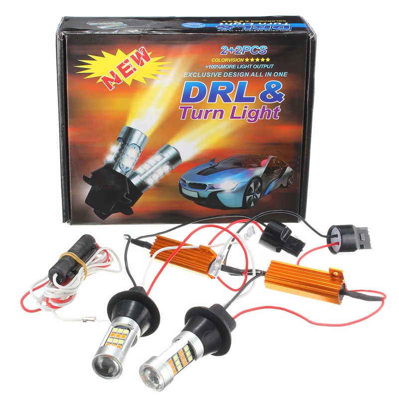
Switchback bulbs plug straight into existing bulb holders.
The white wire just connects the two bulbs across the car. (If you unbolt the 10mm bolts across the front beam, the wire can be neatly hidden out of the way.)
The red wire from the switchbacks connects to the red wire on the controller.
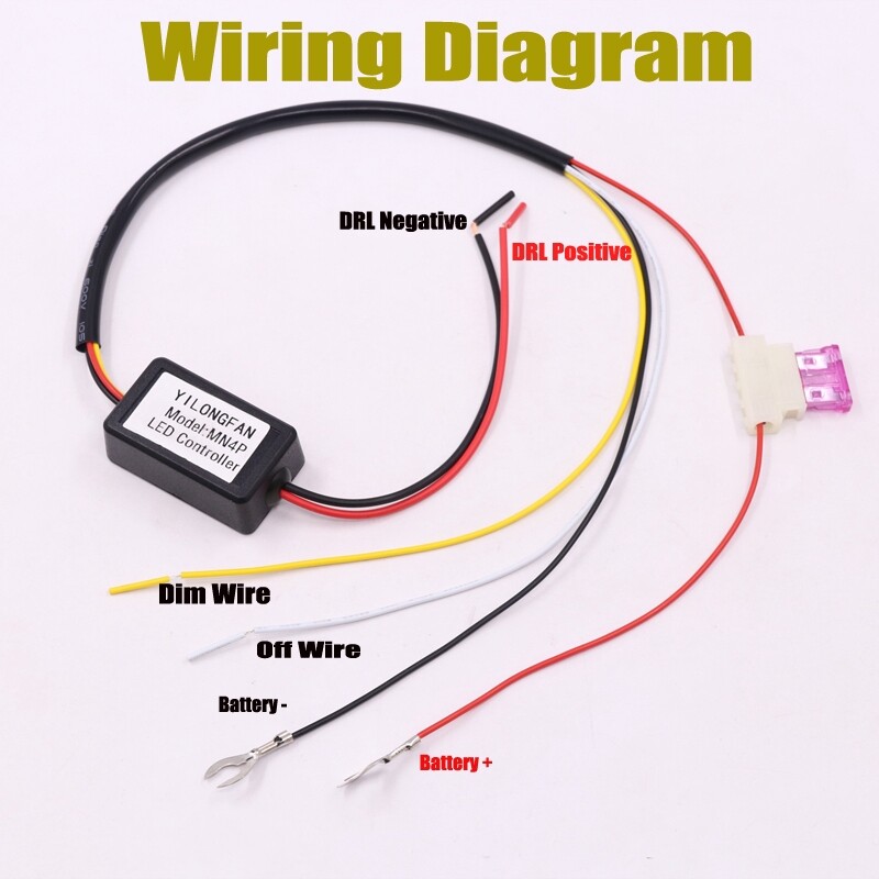
Controller:
Red and black battery leads are self explanatory.
As I said above, the red wire from the switchbacks connects to the red wire on the controller.
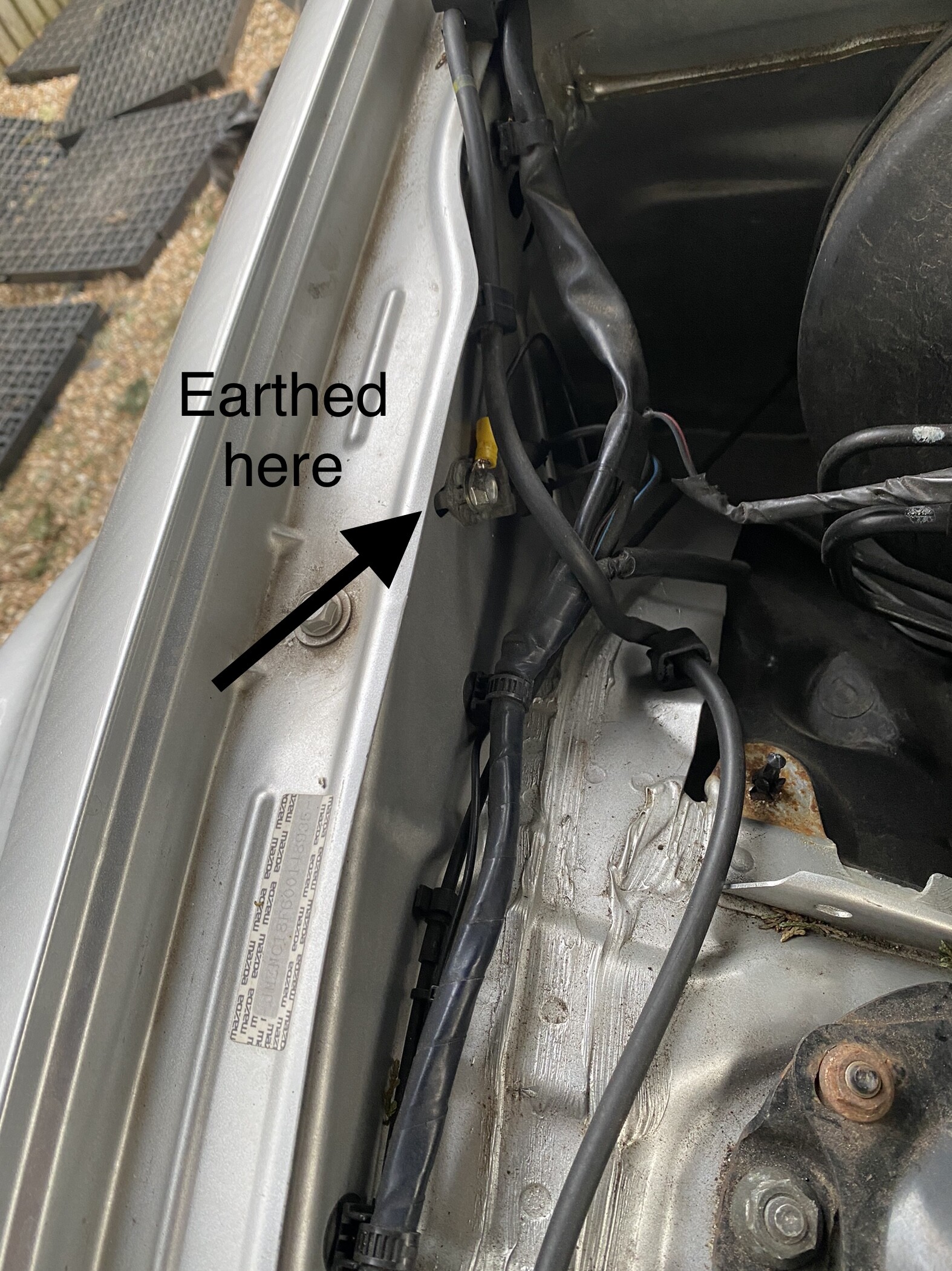
The black (earth) needs to be connected to any earthing point on the bodywork. There is an easy point 3/4 way back on the top of the o/s/f wing. The wiring can then be neatly clipped to the other cabling.
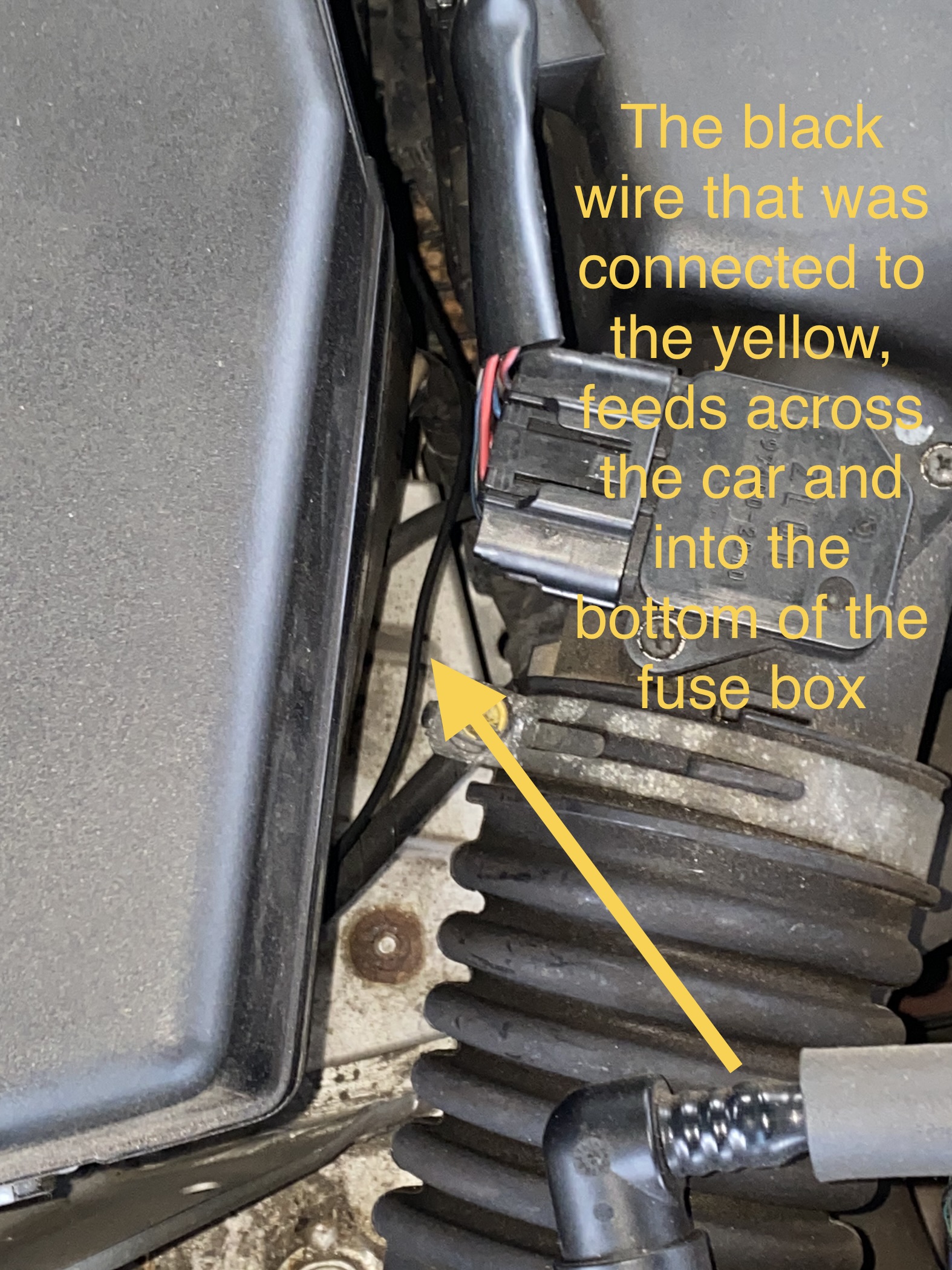
The yellow wire (dimmer) needs to be connected for MOT compliance. I founded the easiest way, was to pick up the purple wire on the underneath of the fuse box. Got the idea from here… https://youtu.be/X41dfRI1w3o
Phil, I looked at your Youtube link. I’m installing bulbs that act as indicators and DRLs, ( https://www.youtube.com/watch?v=ycNJrBsaJtM ) so are they the same as you have fitted?
Your wiring description is close to mine, but I don’t think my bulbs can be dimmed, so I can’t make use of the yellow wire. Instead I was going to connect the white wire on the controller to the dipped beam fuse to turn the DRL off when the headlight is on.
You have exactly the same set up as I have and they definitely can be dimmed.
The link I added was just so you can see where to pick the headlight feed up from. The yellow wire taps into the purple on the bottom of the fuse box. The controller unit detects the voltage increase (headlights on) and in turn, drops the voltage to the DRL’s.
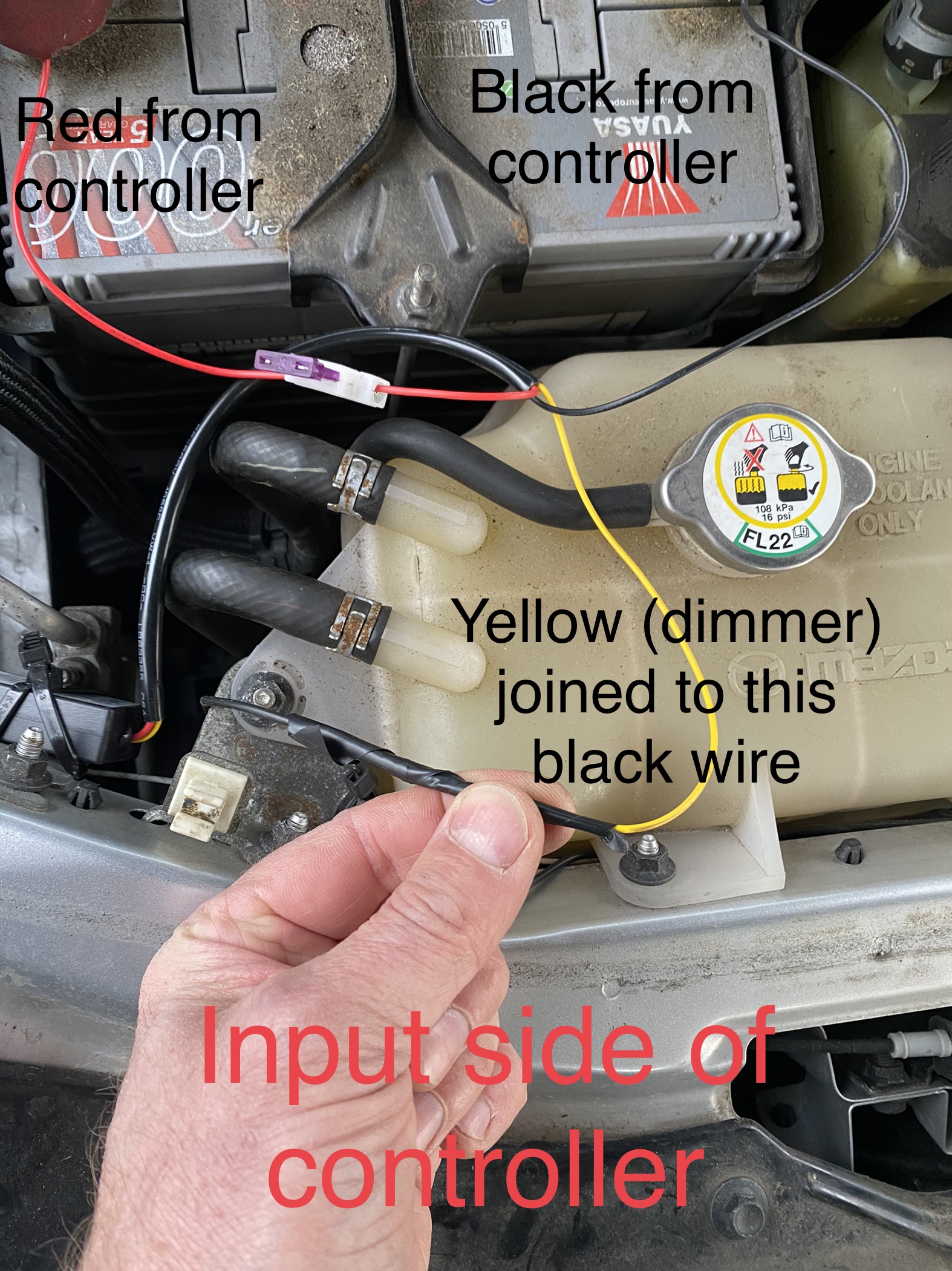
I will try and get some photos of my set up this evening, weather permitting.
I’ve plugged the LED indicators into the old power connections and they work, so it’s just the rest of it to do!
I connected the red controller input wire with a piggyback to fuse 19 (injector) for live supply for the DRLs as soon as the engine is running, and black input wire to earth.
With the white input on fuse 22 (by piggyback) which is LH headlight low beam to interrupt the supply I thought that was it. I was going to leave the yellow wire unconnected.
On the controller output I connected the red wire to the red(white) wire to the DRLs. When the black output wire touched the body there was sparking and smoke.
My guess is the purple wire you mention is connected to fuse 22 or 23 (RH headlight).
If you can take some photos that would be great.
Sorted this out. Wiring is as my diagram, the black output from the controller isn’t connected , it’s capped off to make it safe. I read this post again https://forum.mx5oc.co.uk/t/cheap-daytime-running-lights-drl-fitting-on-nc/115978 and whilst a 5 pin relay is being used instead, noticed that the other output was made safe as it would be live when the headlamps turned on, as will be the case for my controller.
I’ve wired my DRLs to go off rather than dim for now. I’m just glad to have worked out the wiring so I can put the front back on the car.
I’ve ordered a relay in anticipation of the controller failing, and may trying the dimming option then, although I try think that the legislation is that the DRLs go off, not dim.
Hi Clive,
I managed to take some photos of my setup, but glad to hear you’re all sorted.
My DRL’s definitely dim when you put on the headlights. This was achieved by connecting the yellow wire to the headlight feed.
Thanks Phil,
Your setup is similar to mine, although I couldn’t see a white wire from your controller.
I checked the black output from the controller today and it isn’t live, so I must have made a mistake when I initially connected up.
I’m thinking of putting the same DRLs in the rear. I’m pretty sure if the white wire is connected with a relay to the reversing light wiring you get 2 bright reversing lights out of this.
The nearside DRL has started flickering and some LED’s aren’t illuminating. The indicator part works okay.
I’m guessing this will be down to the controller. I’d rather not swap the other DRL to test, as I already have a 5 pin relay.
If it’s not the controller I’ll get another bulb.
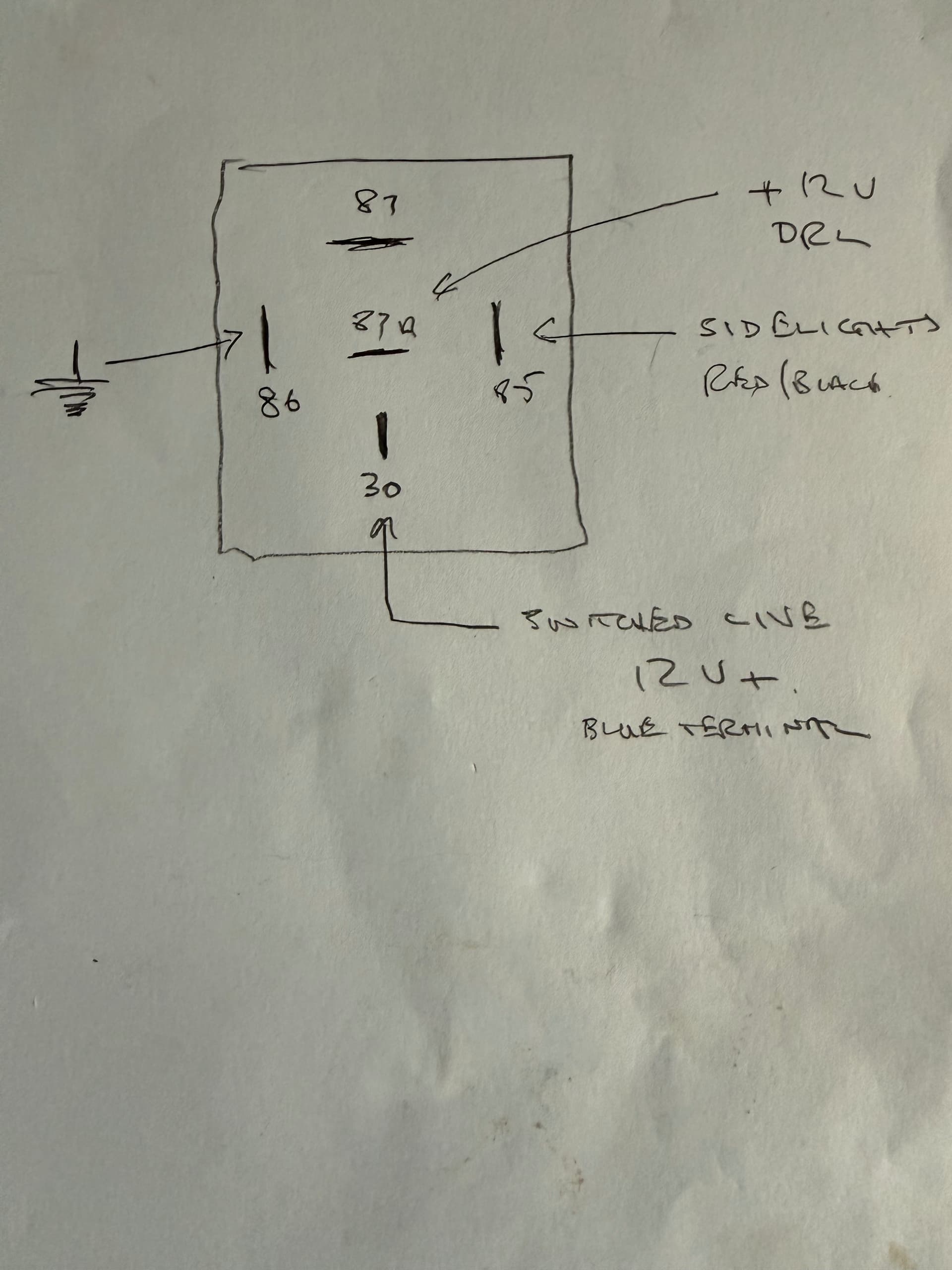
Do I have the wiring for the relay correct?
The controller is wired as follows;
Input positive - connected to fuse 19 (injectors) - move to relay pin 30?
Input negative - earthed to body - move to relay pin 86?
Output positive - to fused 12V source to DRL - move to relay pin 87A?
Output negative (Black cable) is unconnected - nothing to connect to relay.
Yellow cable on controller (marked D) is unconnected - nothing to connect to relay.
White cable on controller (marked K) is connected to fuse 22 (LH headlight low beam) - connect to pin 85?
I’m looking to do the same and have the same LEDs as yours, but didn’t realise I needed a controller to turn them off when the headlights are turned on..
No, I’ve just unclipped the DRL wires so just the indicators work. I’m going to swap the bulbs over to check if it’s the bulb or something else, but suspect it will be the bulb so I’ll need another set. A job for the winter when I get in the garage, and I can see if I’ve got the relay wiring correct.
Just done mine, relay fitted on near side wing, used the switched live from the blue plug for positive feed and tapped into sidelight feed nearby to switch the relay and turn off the DRL’s, from memory the relay is wired as shown previously in this thread.
Nice and tidy, works well, removing the orange lens from my NA sidelights was an adventure, but easy once I gained confidence.
Best thing I did was modify the flasher relay, then I was able to dispense with the ballast resistors.