I’m looking for technical help or recommendations on: __fitting above.
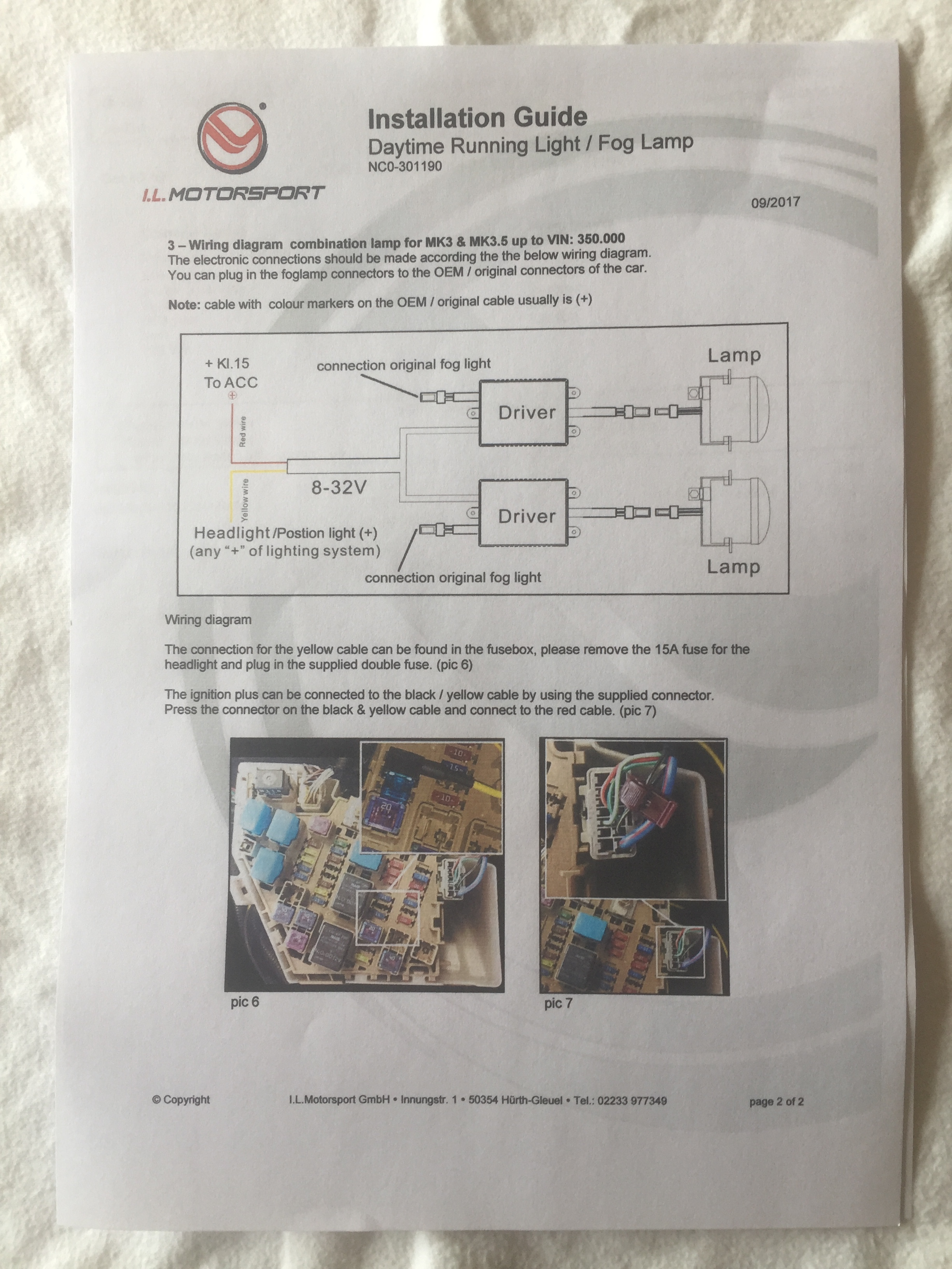
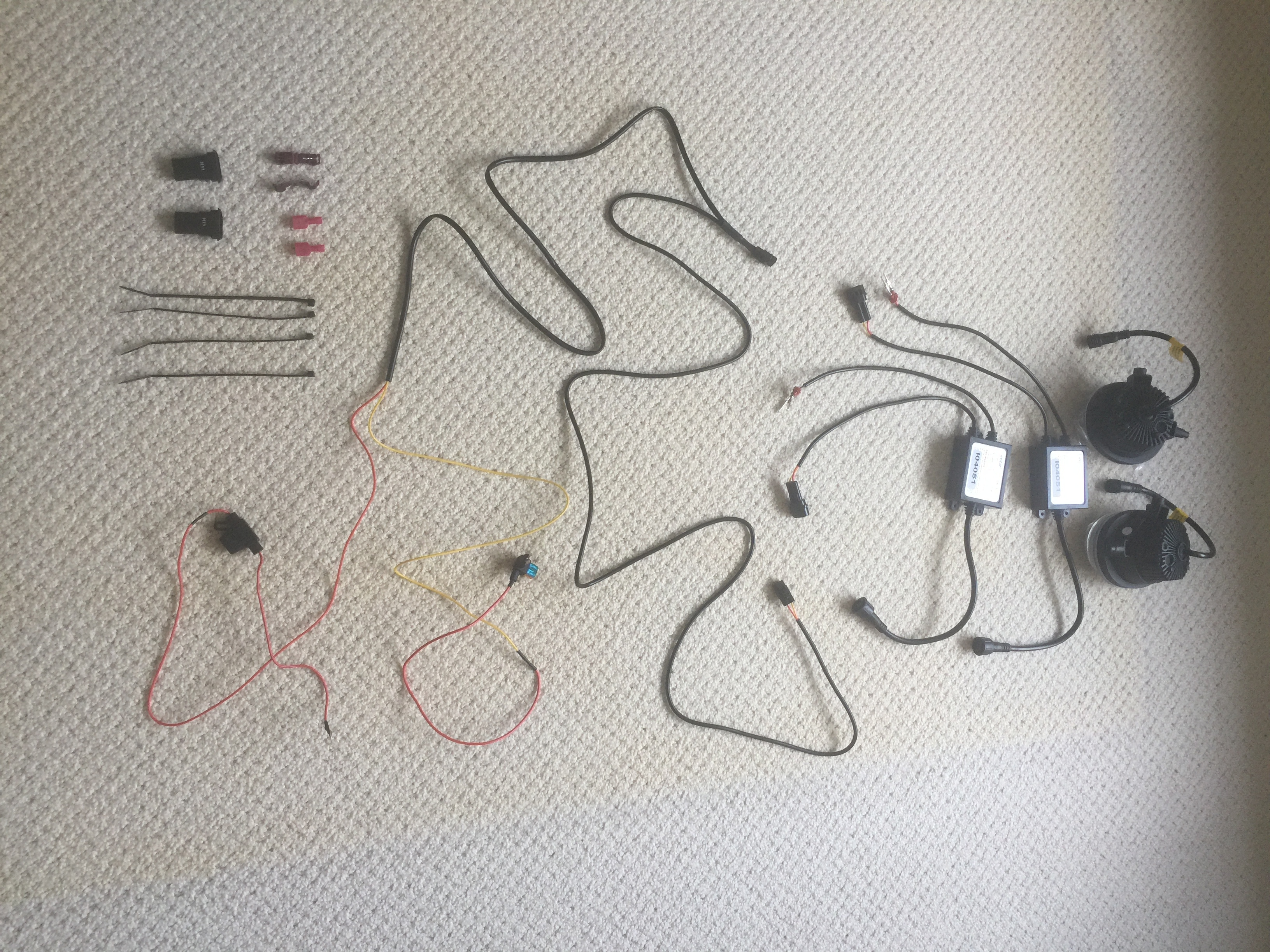
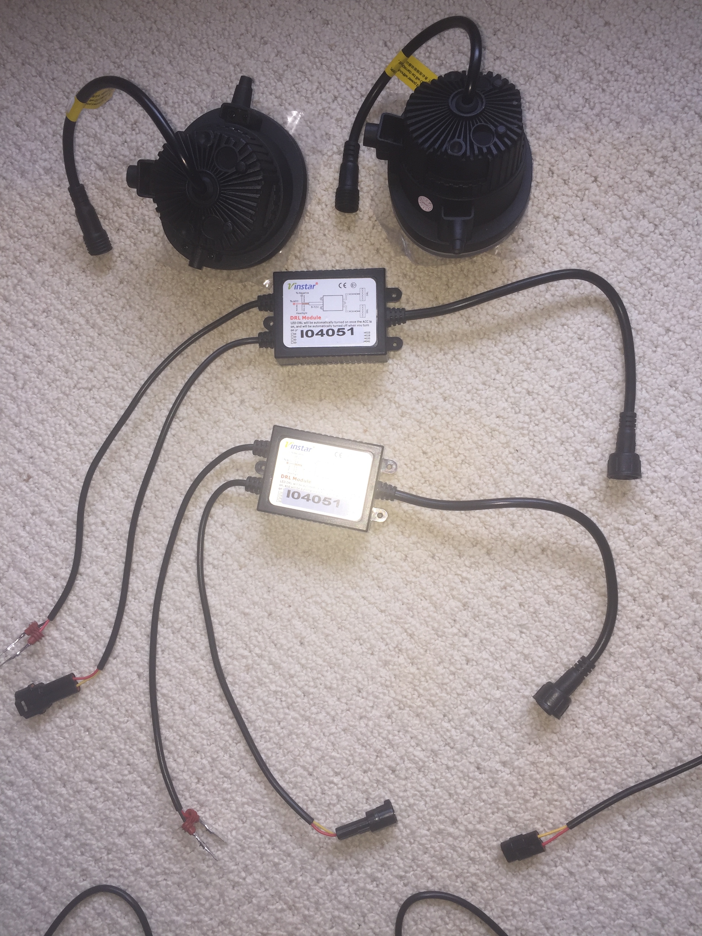
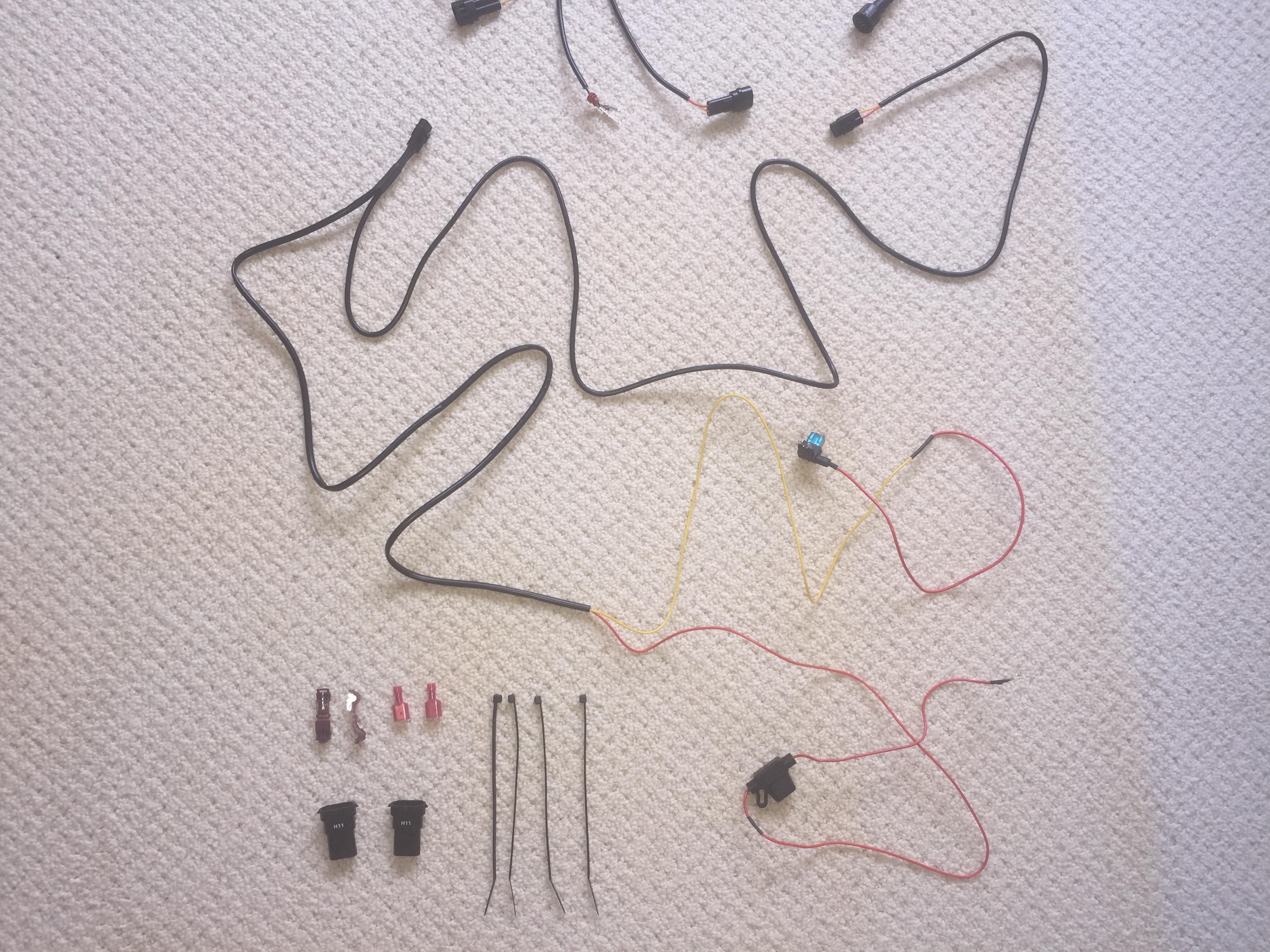
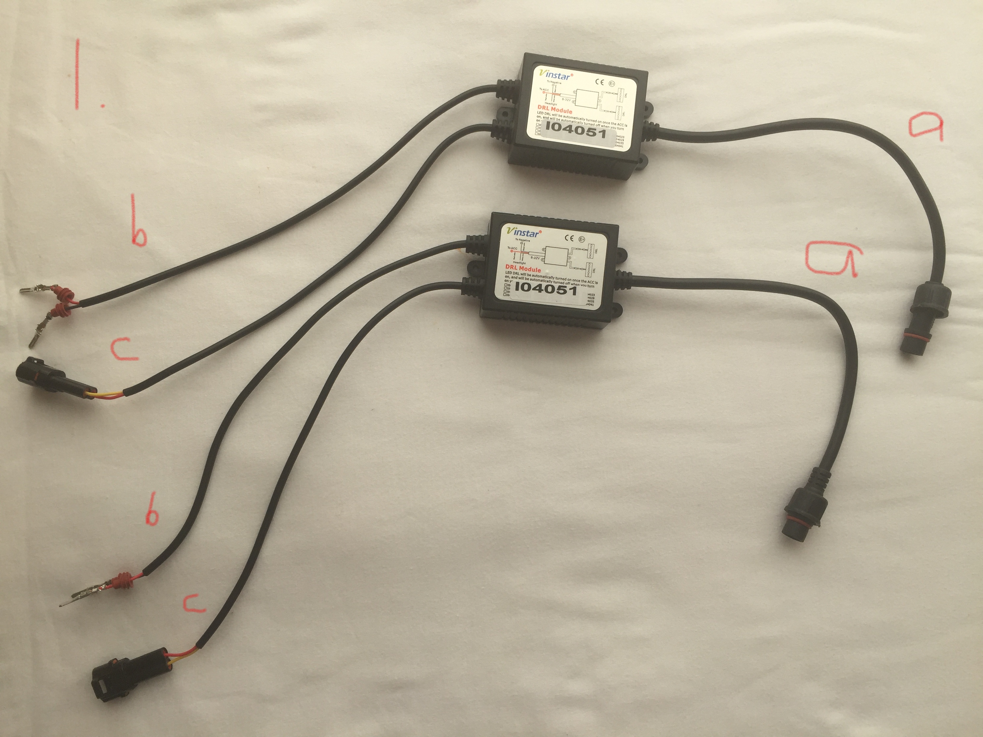
This kit is the one that normally retails from MX5 Parts for £177.56 and is suitable for all Mk.3’s and Mk.3.5’s if OEM fog lights are already fitted. As it was a 10% off weekend and it is described as ‘simple to fit’ I decided to treat myself. I don’t anticipate any problem in actually fitting the units into the car but then comes the electrical bit. I’ve attached some pictures of which the first is the instruction sheet showing a fairly simple wiring diagram. The subsequent pictures show the kit and connections received (one showing everything plus a couple just a bit closer). To say I am bewildered is an understatement and I am afraid that the wiring diagram does nothing to help me install the electrics so the plan is now to install the units then seek an auto electrician. Before doing that though I have experienced what a wealth of knowledge there is on this forum so I thought I would just enquire whether anyone has either done this or is able to explain what has to be done in terms that someone with (very) limited electrical knowledge could understand.
Grateful for advice of any sort and best regards to all MX-5 fans.
In this instance it means Accessory, and the diagram shows it connected to the wiring coming from the IGN relay. Connect to battery and the DRLs will stay on until the battery runs flat. Connect to IGN and they can only be on when Ignition is on, then if headlight is on the driver sees that and DRLs should dim or go off.
Fogs should work as fogs regardless.
The diagram makes sense, and the plugs can only connect one way, The tricky bit is making sure you use the correct connection points in the fuse box.
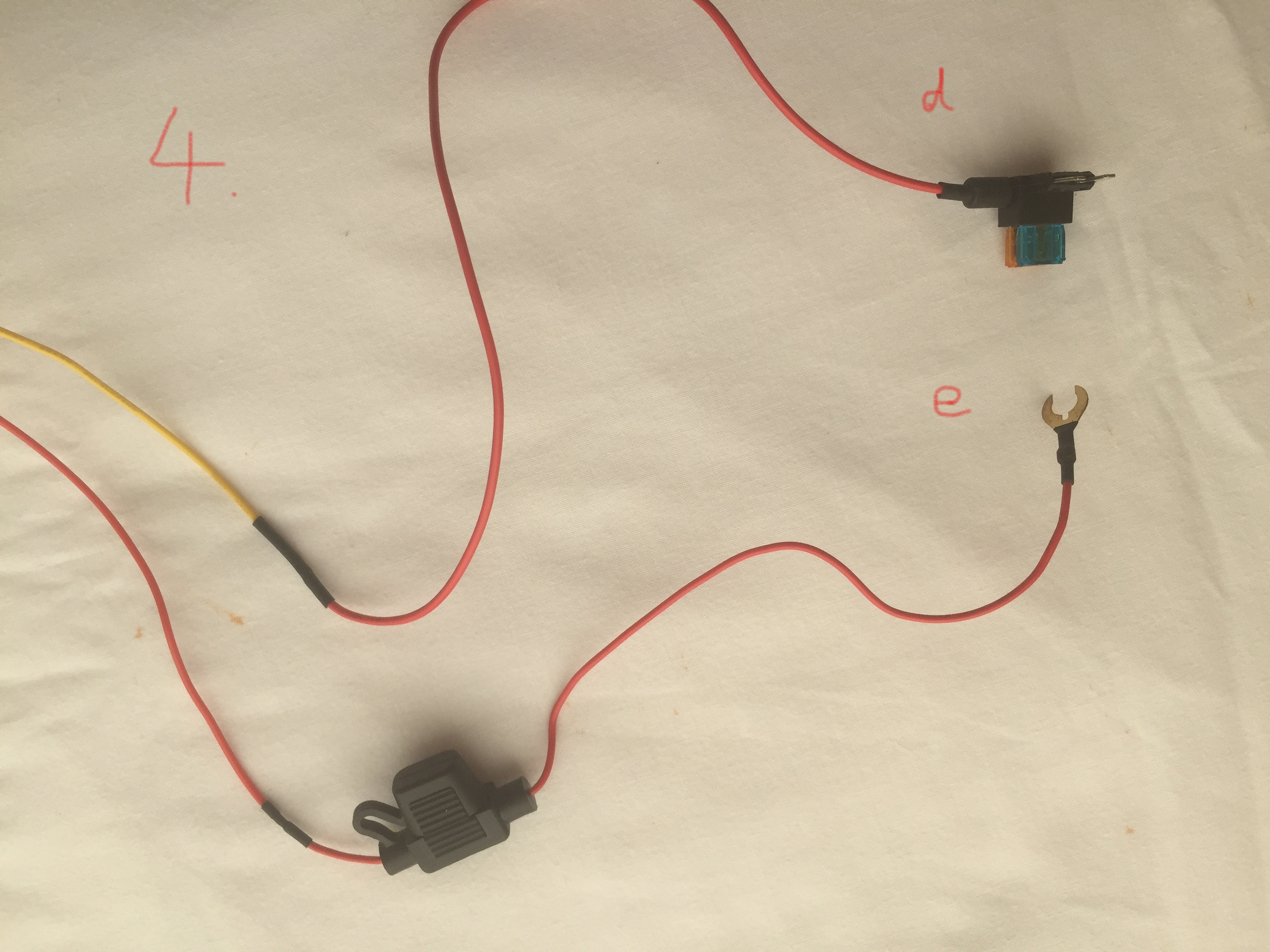
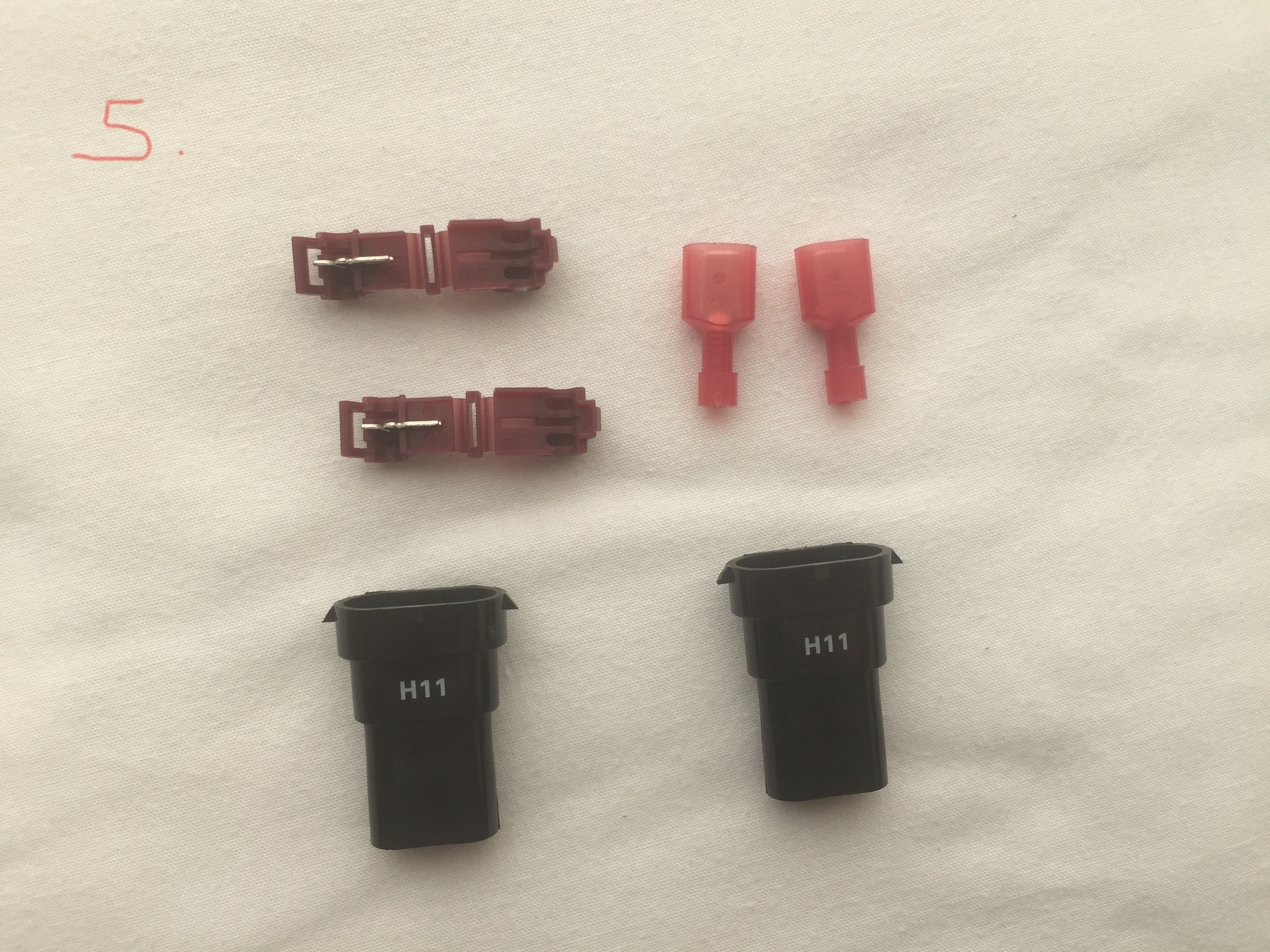
I’d guess that you need to cut the ring terminal (e) off the red wire and use the “electro tap” (mauve bits in picture 5) and spade terminal to connect it to the wire in the fuse box. Are you familiar with the use of the electro tap?
This bloke is using a different brand but the concept is the same.
Please, please, please don’t ever use these T-Tap type connectors on a car.
They cut partway through the wire you’re connecting to (possibly reducing its current carrying capacity) and do not resist vibration very well. They really are the worst sort of bodge imaginable.
Do the job properly and solder the connectors, and then put heat-shrink sleeving over them. Finally, some self-amalgamating or fabric tape around the wires will make it look like it’s all part of the factory loom, and keep out moisture and dirt.
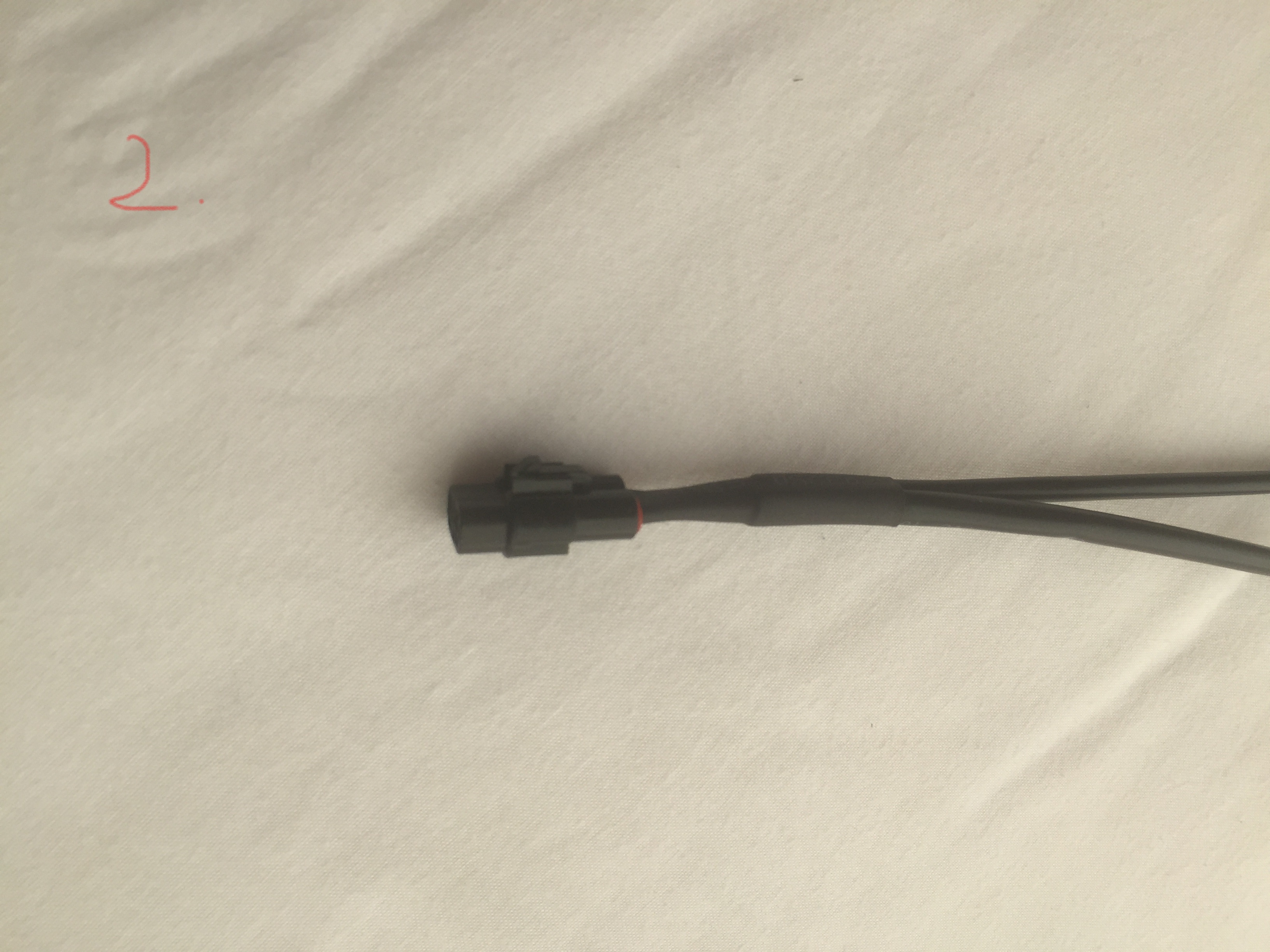
The pairs of pins (Pic 1, b) go into the ends of the Y lead (Pic 2). Make sure the (b) red wire goes to Pic 2 Y red wire in the pairings.
The Yellow lead is simple.
Its joined-on fuse adaptor goes to any one of the 15A Headlight fuses as shown in their instructions.
The ‘Red wire’ is the joker in the pack.
The Black/Light-Green MX5 wire they show the vampire tap going to is not ideal, damage this lead or pop its fuse and something in the car stops.
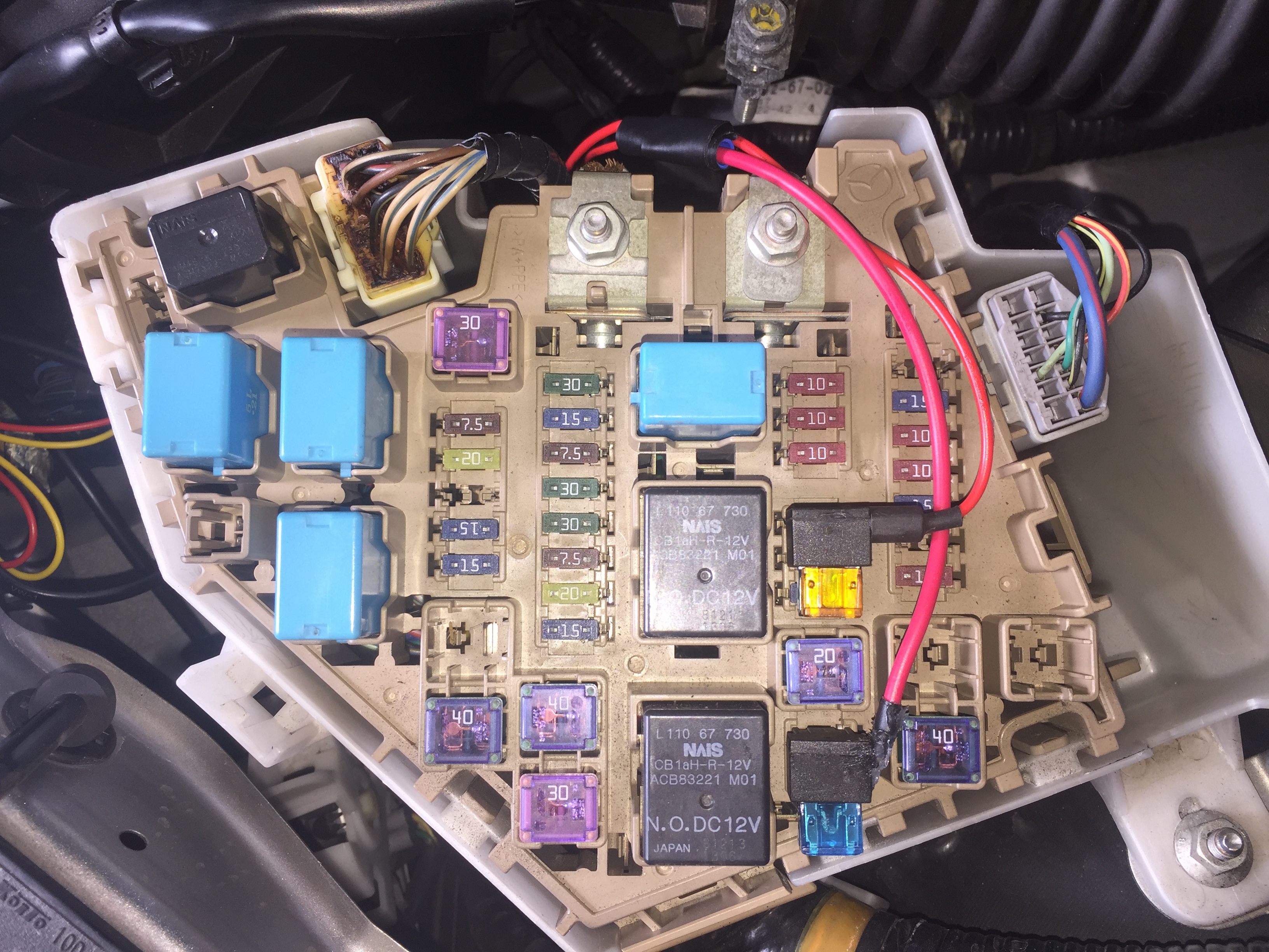
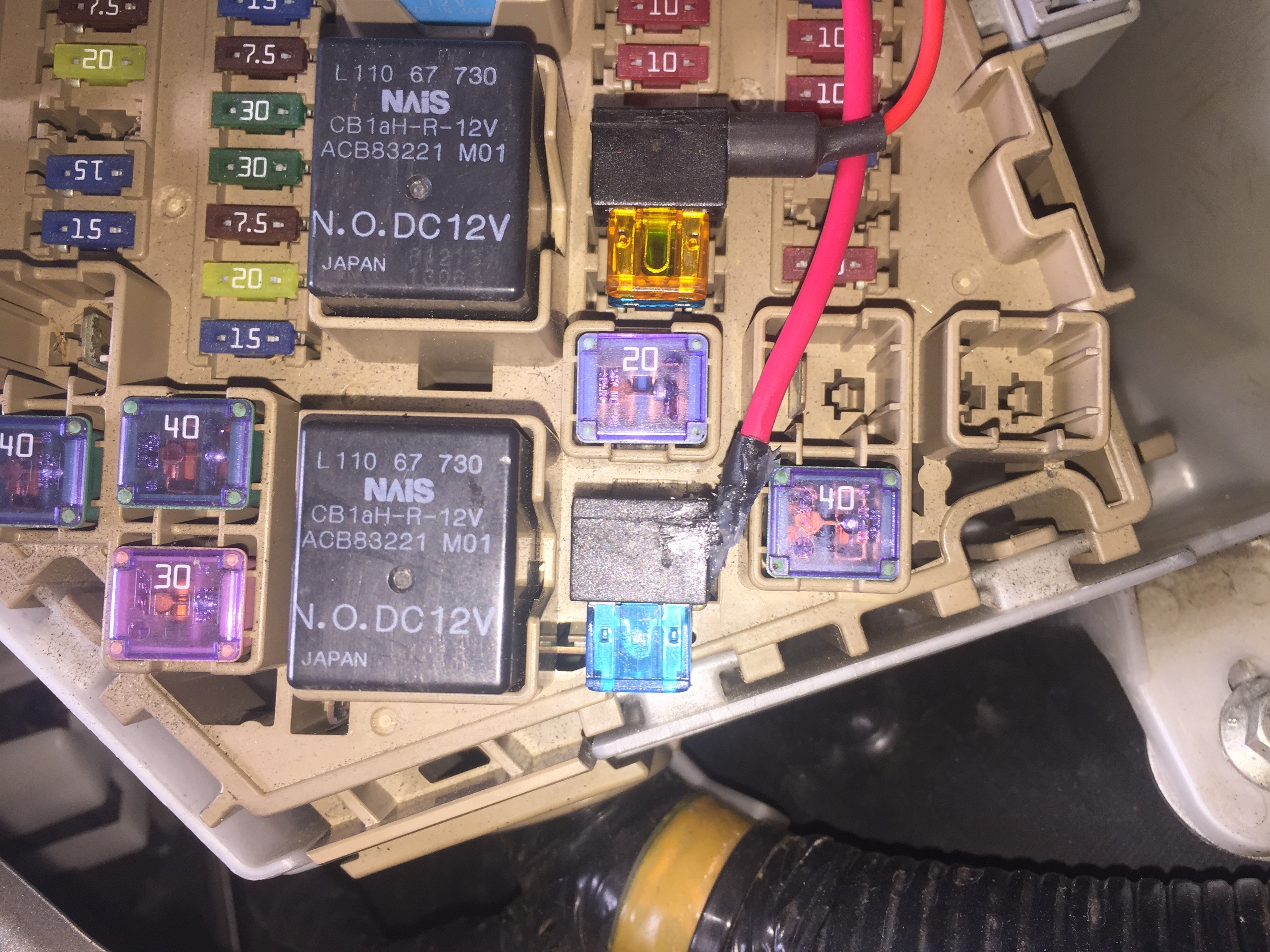
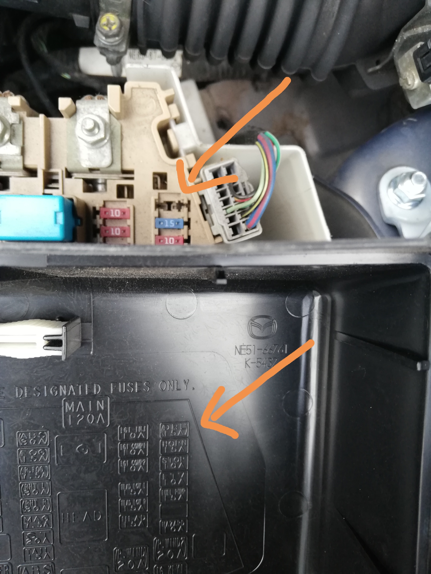
Ideally the ‘Red wire’ connection should go to one of the outputs from the ‘Ignition’ relay, listed as fuses (P.WIND 20A), ENGINE 15A, WIPER 20A, but unfortunately the usual ‘mini fuse’ piggy-back adaptors all foul on the IG KEY1 40A fuse or the new fuses foul the fusebox cover.
Picking up on one of the ‘Main’ (EG1) relay’s 10A fuses would be better, IF the DRLs don’t take too much current!
(See inside the fusebox lid for a map of what the fuses are.)
The small fuses in the engine compartment fusebox are all the ‘low-profile mini fuses’ (APS or ATT) but an ordinary ‘mini fuse’ (APM or ATM) will also fit, just sticks up a bit. The piggy-back adaptors are mostly ‘mini fuse’ (very few low-profile types). Most have a long hard moulded arm where the flying lead comes out for the new accessory, and it is this arm that fouls on the 40A fuse as mentioned above.
Here is a picture showing three relevant relays, each one then feeds three fuses. Both ‘Main’ and ‘Ign’ are only on when the car is switched on to run, so fuses on them can be used as piggyback points. However the Main (EG1) relay is only rated at 20Amps, less than half that of the two biggest ones which I’ve found are rated variously by different on-line sources from 50A to 70A.
The extra bits and pieces are supplied to offer you more connection options, you don’t need to use them all.
If you don’t use the vampire tap and instead choose to piggyback on one of the EG1 fuses, then another piggyback adaptor will need to be added to the red wire instead of the in-line fuse fitted now.
Thanks Philip. I read your views and thought there’s a bit of a perfectionist who believes that a job should be done properly which is all very well if you have the skills which I definitely haven’t. However they also made me do a bit of online research and it quickly became apparent that you are not a lone voice in this respect. I was pondering how to cope with this when Richard FX comes to the rescue. Just have a look at his brilliant post and again many thanks for the good advice.
Richard FX not only have I understood your explanations I can say that it has given me the confidence to tackle this job myself. I’ve checked all the connections and now understand how they all work. With what you have explained and taking into account Philips remarks above I intend to get another piggyback adaptor and pick up on one of the EG1 fuses. I will check the current used by the DRL’s first getting in touch with IL Motorsport if necessary. They are LED’s so I am hoping that it will not be too high. Thank you very much indeed I am very grateful and in awe of your expertise.
RichardFX I am pleased to say that the DRL/FogLights are installed and operating perfectly, largely thanks to your invaluable advice. As anticipated the physical install presented no major problems but I was keen not only to avoid the use of the vampire tap (as recommended by manufacturer) but also to utilise what you described as the ideal connection (one of the outputs from the IGN relay). Therefore as the piggyback connectors came in a pack of five I thought could have a try at altering one of them to see if I could get round the problem of it fouling on the IGKEY 1 40A fuse. So I split off the rubber cover and carefully pared away the moulded plastic arm with a sharp knife until I could nip it off exposing the metal arm and attached wire from the adaptor. It bent back almost 90 degrees fairly easily taking care not to break it
of course, After a small wrap of insulating tape and a good covering with clear silicon I was able to fit it in the fuse box as you can see from the attached pictures. What I now need to know is ; Is this a reasonable practical solution or a daft and maybe dangerous idea? I would very much value your opinion, and indeed any other opinion, for which thanks in advance.
I would have done much the same, maybe finished it with an epoxy for a bit more strength rather than silicone.
I used a low profile mini fuse piggyback on my recent dash-cam install on the Mazda3, mainly to not stick out too much. But lack of space meant the bend-it mod would have been impossible so I ended up with the two fuses in series - as if I had been using the Acc socket in the car. Alas I’ve not seen this adaptor on offer elsewhere.
Just be careful with fitting the cover for the fusebox!
Thanks Richard. That’s a relief. No part of the new circuit stands proud of anything already in the fuse box so the cover just clips on as normal glad to say.
I am going to fit some cheapo DRLs that simply have a powered and ground connection. I could easily just run this to a piggyback fuse on to keep them on all the time with the ignition. But, I need to get creative if I want to have them go off when the lights are turned on.
So, is there an easy way to do this? I presume I need a relay that I connect to a piggyback headlight fuse which allows current to flow from the piggybacked ignition fuse when the headlights are off, and cuts the circuit when the headlight is on?
Is there a tidy way to do this inside the fuse box, or do I need to tap the fuses as pictured above and run this to a relay I mount elsewhere (probably hot glued behind the bumper somewhere).
Or… Just spotted I have an empty slot for a 15A fuse which is labeled as DRL. Has anyone checked if this is wired up ready to go as a powered connection for the DRL?
Not sure how that works… read up on relays tonight and think I need a Normally Closed Make&Break relay, with the energising feed coming from the headlight fuse tap, and the draw for the DRL coming off an ignition or acc tapped fuse. When the headlights go on, the relay is energised and then opens the DRL circuit thus switching them off.
Have I got this right?
Seems to be plenty room to wire and mount this in the fuse box area.
This is intended to go to Mazda’s DRL control module, not directly to the lights. I don’t know if UK cars have this module.
One side of that fuse is always live.