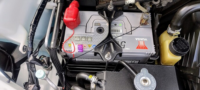
About to fit the MX5 Parts kit and this thread has been really useful. Can I ask those who have fitted the kit where and how did you mount the 2 lamp driver modules.
I thought there were a couple of options the first one being the ledge on the inside at the bottom of the front bumper. They would be securely held here just by a good 3M sticker as it’s a nice flat surface and there would be no need for screws. I decided against this in the end just in case there would be a future need to remove the front bumper for some reason. I ended up placing them on the inside (engine side) plastic panel which is convenient for all connections. I placed it with a 3M square sticker and put a self tapping screw at each end in the mounts provided. It is very light and seems to be very secure. Everything is still working fine anyway!
Jaydoubleyou thanks for that. I’ve fitted the light assemblies and agree that the control units are very light. I’ve decided to mount them with self tappers onto the fog light bracket as I need to remove the plastic panels in the near future to waxoyl the wheel arches and chassis legs and don’t want to disturb the new wiring. Just got to connect to the fuse box and job done. All in all very straightforward with the information you have provided. Agree the instructions provided with the lights could be a lot clearer.
Having now completed the fitting of my MX5 Parts fog/drl’s as Jaydoubleyou found the mechanical installation is straightforward but I also hit electrical problems.
Firstly I tried using a micro piggyback fuse off the wiper fuse for the ignition controlled feed hoping the wire would pass down the side of the 40amp relay. However this didn’t work so stripped back the fuse holder cable moulding only to reveal a poorly crimped cable. Once this joint was soldered and wrapped in tape the cable did pass down the side of the relay.
The other problem I found was that the foglight connector is supplied as a holder into which you insert the pins that are crimped onto the cable. Struggling to get one light working I found that when the assembled connector was pushed into the foglight connector the pin was moved such that it looked like it was connected but actually was not making contact. You do need to use a small screwdriver to make sure the pins are pushed well in after the casings have clipped together.
However having sorted out these issues and everything works fine I feel a lot safer and hopefully avoid other road users not seeing me coming in a low dark red car.
Hopefully anyone else tackling this can follow the above comments and be aware of the potential problem areas.
Glad to hear that you’ve got it sorted. Although I didn’t have a similar problem with the connector I did wonder why it should come like that rather than be assembled already. I agree with your final remarks too. There have been times when I have wondered if my low grey (aluminium silver) MX5 was actually invisible and I think these DRL’s will be a great help.
Well done on solving all your ‘snags’ and all the best. Another chance also to thank RichardFX as I would not have been able to do it without his input.
I know this is quite an old thread, but I’m just putting these on my car now.
I’ve got the new units in but just want to make sure when it comes to the wiring.
Is it just a case of snipping off the end of the red wire with the inline fuse and spade terminal and then putting on a piggyback fuse instead and then using that…?
Sorry if it’s a stupid question, first time I’m attempting anything electrical on a car like this
Further up the post it suggests not using the supplied vampire clips and to do it properly and connect it in to the fuse box. The OP used a piggyback fuse to do this but I’m just not 100% if they removed the end off the red wire with the inline fuse and spade terminal…
It can only be that wire as far as I can see as I know where all the others go… just don’t want to start cutting and soldering the wrong wire…
The previous posts are really informative with good pictures, I just don’t know enough to go off them 100%
Sounds something I’d be concidering on my NC. Do you have any before and after pictures we could all see, with the drls on?
Here you go, how I did it, all you need to know with an NC1 ,with pics at the end showing fogs, drls, both .
That’s perfect RichardFX, exactly what I needed, appreciated ![]()
