Fitted DRL+Fog combination lights to NC - MX5Parts Vinstar kit

Fitting Vinstar DRLs in a 2008 NC

After a top-down drive in the sun to Cliveden early last week and needing to put my lights on because the lanes were so dark with overhanging trees and the 4x4s coming the other way seemed to want all of the road, I’ve bitten the bullet and fitted the Vinstar kit from MX5Parts.

The Fogs take 0.9A each, the DRLs 0.5A each from 12V on the bench, and dropping to a bit less as the volts rise to 14V when engine is running to maintain a constant current on the LEDs themselves.

It is not as simple as the instructions might suggest, and I think I have a better place to take the DRL power feed from in the fuse box.
Further, the Vinstar fogs in the DRL+Fog assembly point just a bit too high, and the mounting bracket MUST be modified (as suggested in the Mazda service manual) to make them adjustable enough to be usable.

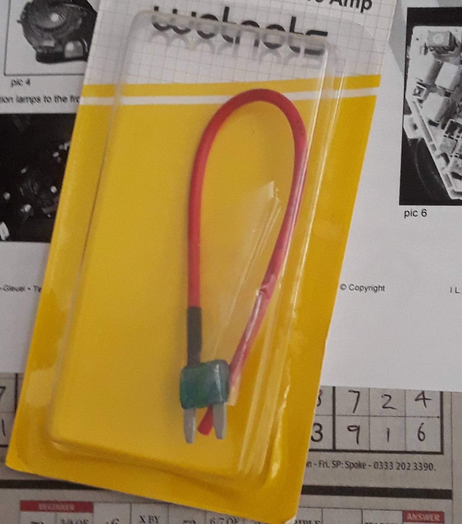
The kit of bits supplied.

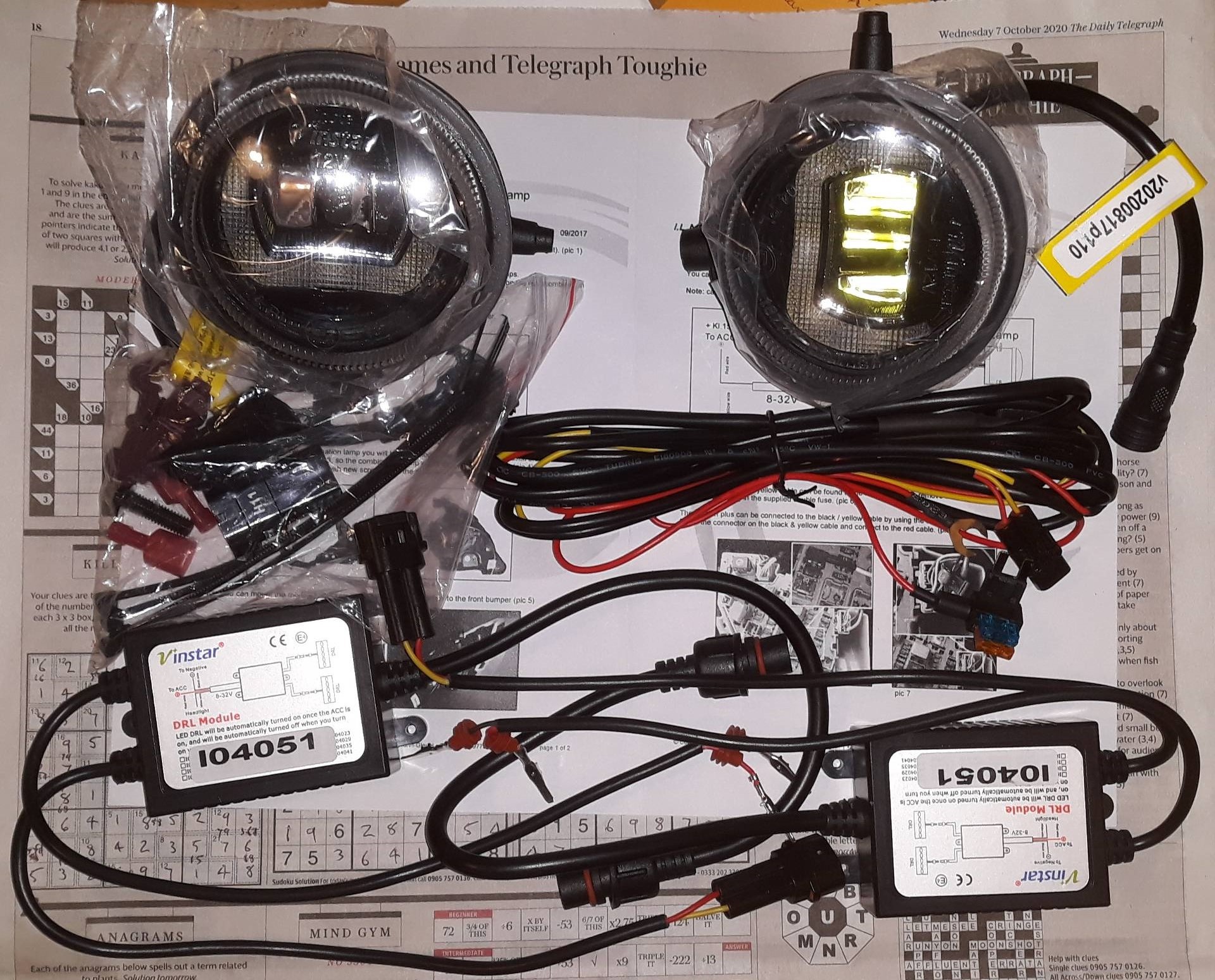
I tested it all worked on my workbench before taking the car apart. All good.

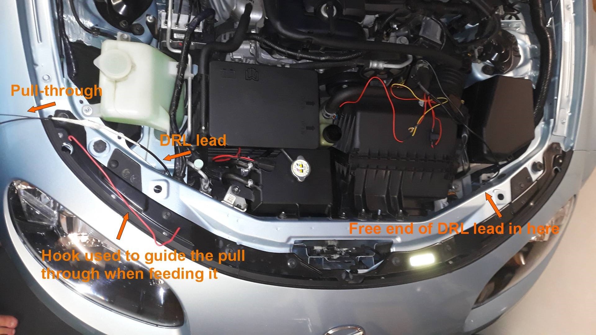
First of all I needed to thread the new DRL lead through the cross member where the bonnet catch is, this is quite easy with a pull-through (a bit of old 1.5mm copper house wire), and then the lead can sit on top of a fat wiring harness with a few cable ties to prevent it walking. I started by the fuse box and worked it through. The red hook wire was very useful in helping to steer the pull-through when I threaded it through to begin with.

I began taking the car apart on the drivers side, turned the road wheel fully out, and this gives just enough access. Taking the road wheel off would make life easier, but not reduce the overall time. Removing the lower splash shield is quite simple, 11 fasteners removed and it drops down.

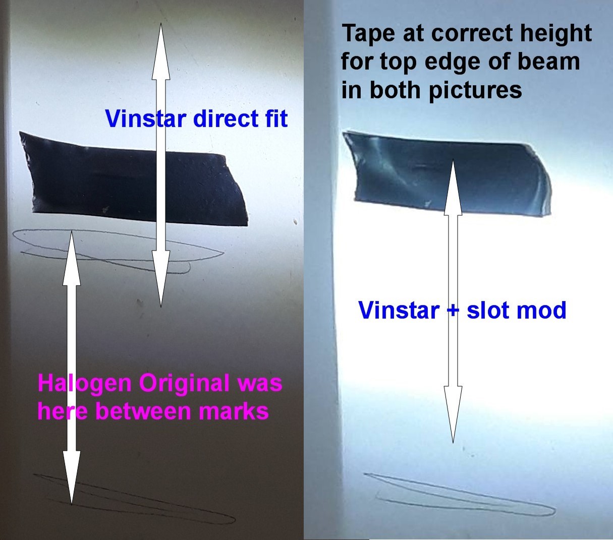
Before removing the original fog light I marked its beam pattern on a board a metre away in front of it for future reference, just as well.

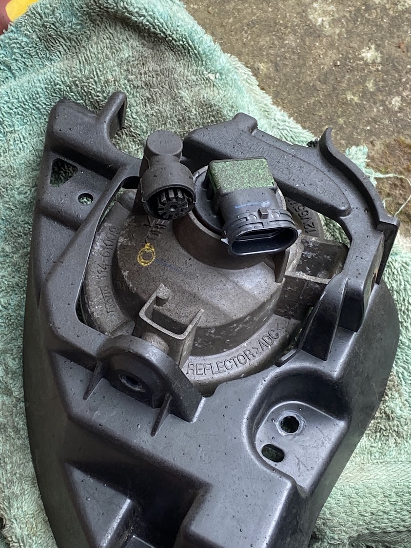
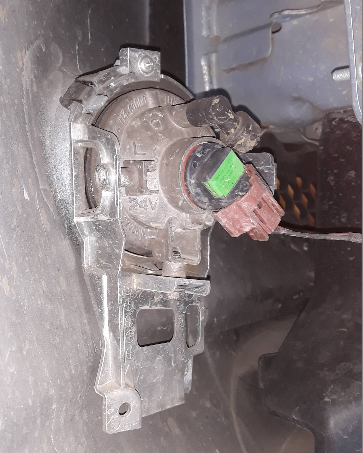
This pic shows the original L fog light on the passenger side, driver’s is almost a mirror of this. Each one is held in a bracket by two machine-screws, one is the inboard pivot and the other is the adjustment clamp, easy to remove just be careful not to flex the bracket too much. The outer pivot does not have a screw, and would be awkward.

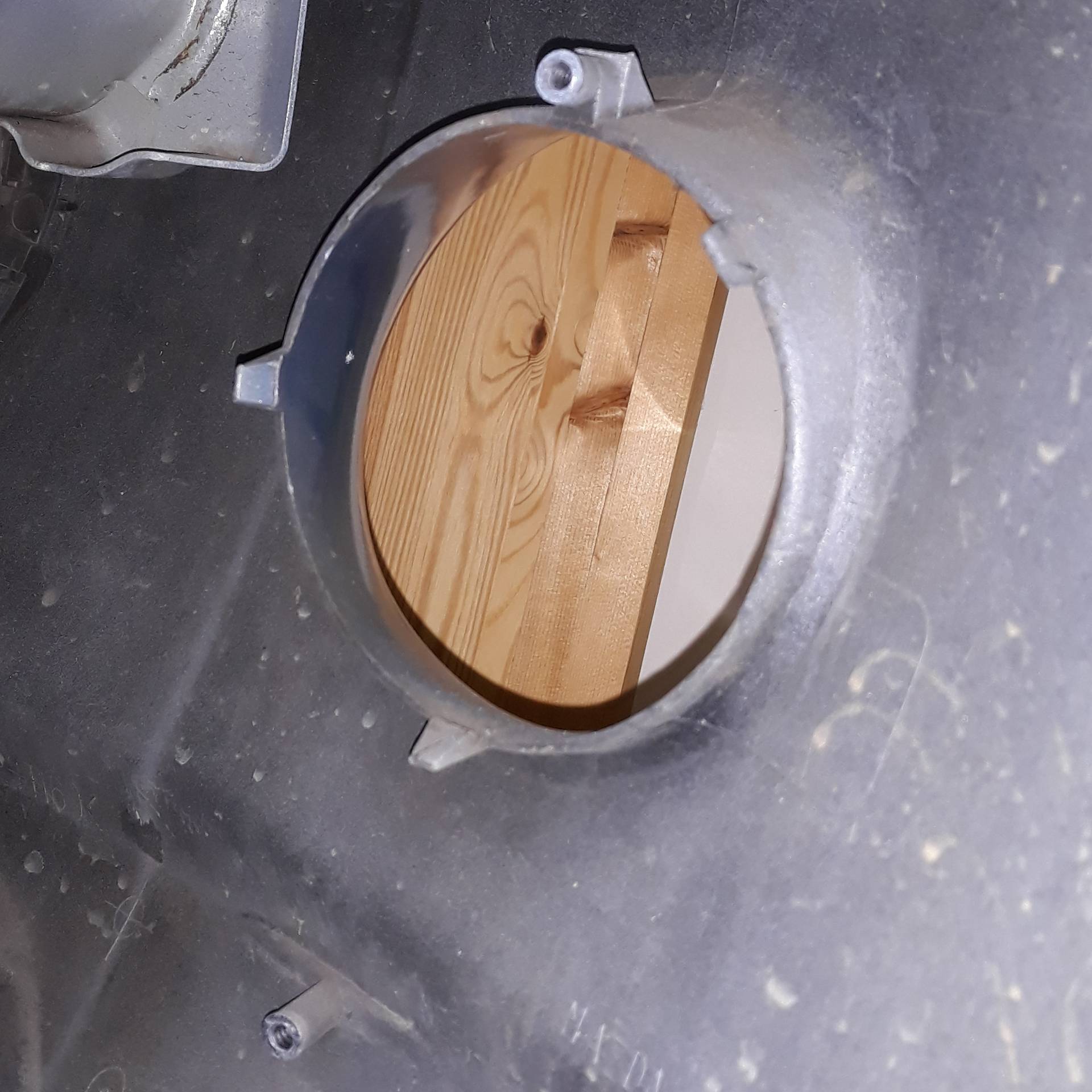
I tested the R Vinstar in the bracket as a simple fog light, no DRL connection yet, and discovered it pointed too high. Mazda say to file out the bottom fixing hole into a slot to provide a range of adjustment.

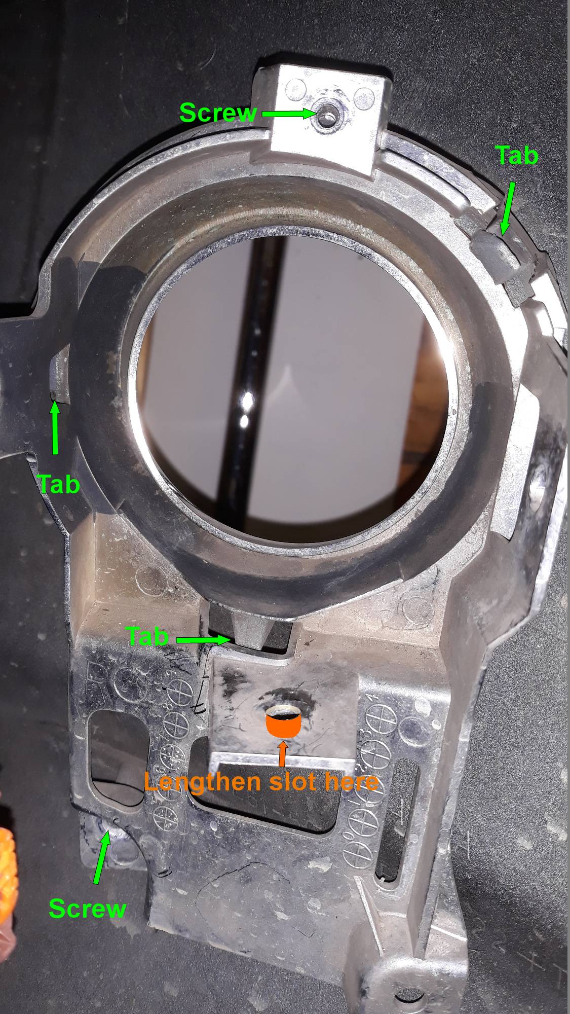
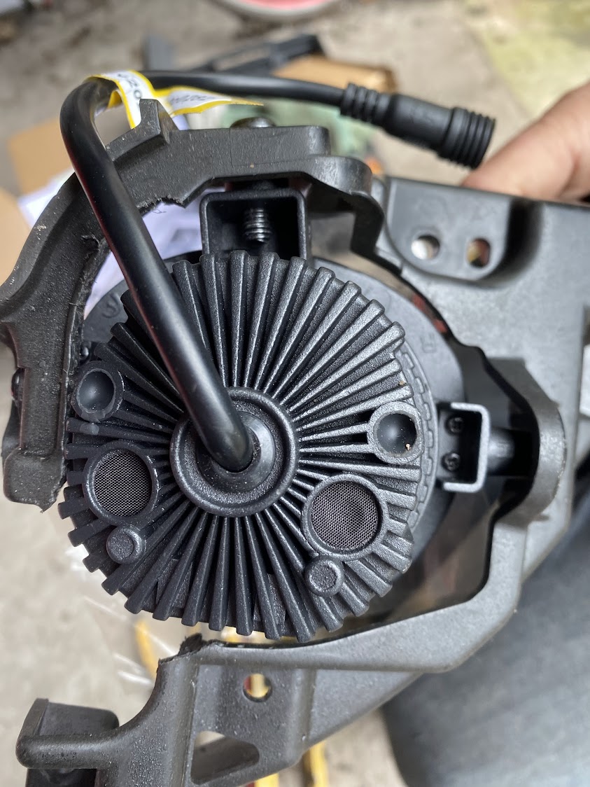
I decided to take the bracket out of the car to do the filing, two self-tappers removed and three tabs pushed aside and it comes out quite easily. Underneath the bracket Mazda have relieved the moulding at the adjustment to show the limits one might use. This picture shows what is holding the R bracket.

This picture shows the beam throw before and after adjustments.

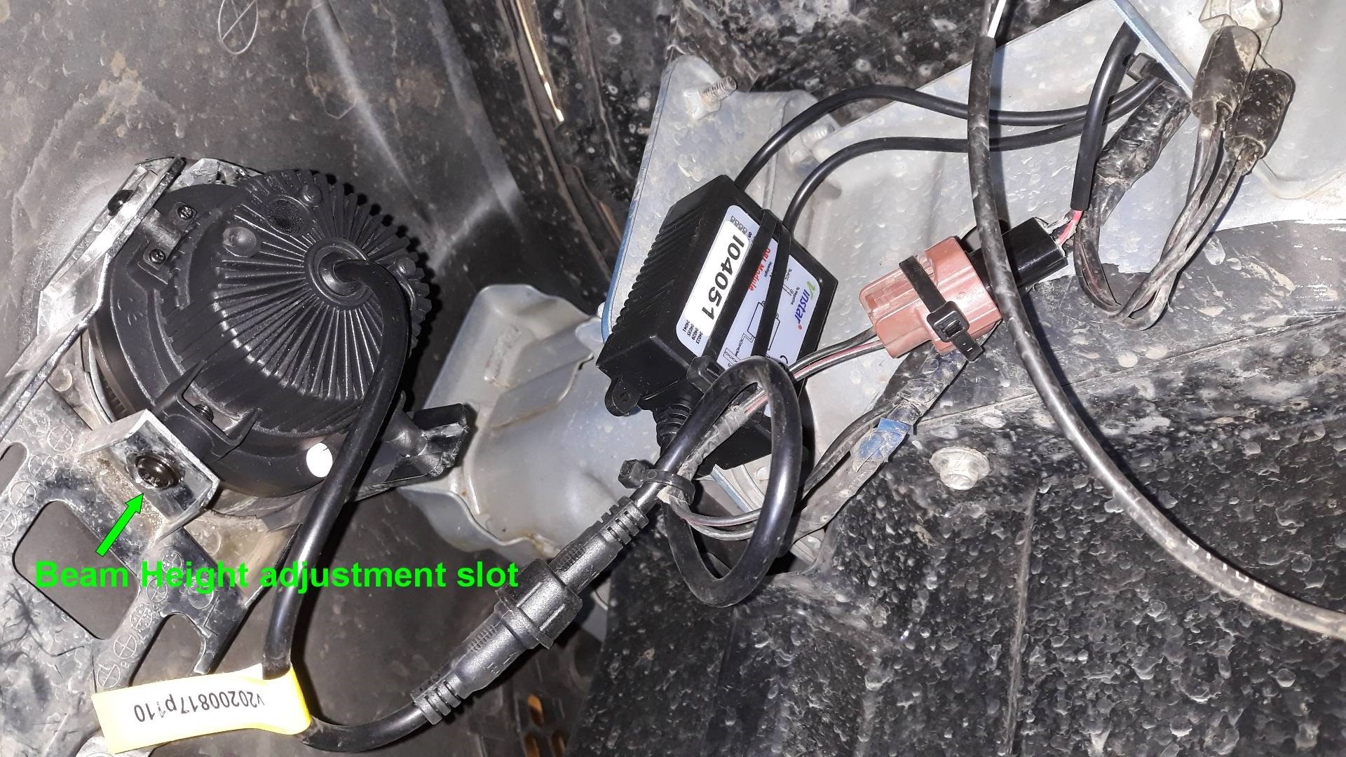
I then wired in the DRL leads and tidied everything up with cable ties to prevent it vibrating around.
Repeated the operation on the passenger side, and here is a pic looking up at the installed L Vinstar and driver box and all the extra leads, compare this with the earlier picture above, a lot more cluttered.

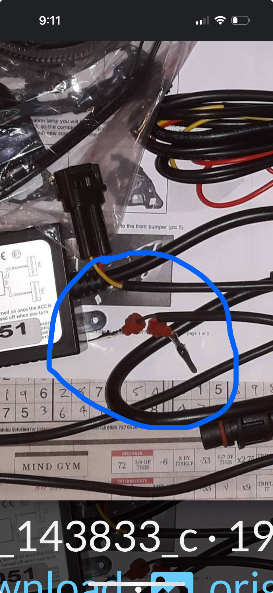
Then I routed the last bit of the DRL lead around and into the fuse box. I cut off the surplus, several feet, and kept the in-line fuse for the Red lead (DRL power) and soldered it to this 15A breakout fuse in the 15A slot next to the IGN relay, so the DRL comes on with the Ignition, not the ACC.

I also shortened the Yellow lead going to the piggyback fuse switched by the Headlight relay. I used these handy solder+heatshrink+hotmelt splices to the cables in the car, a lighter is best, a match can be sooty. The end result looks like this.

Three pictures in one. For Fog on, or DRL on, or both Fog and DRL.

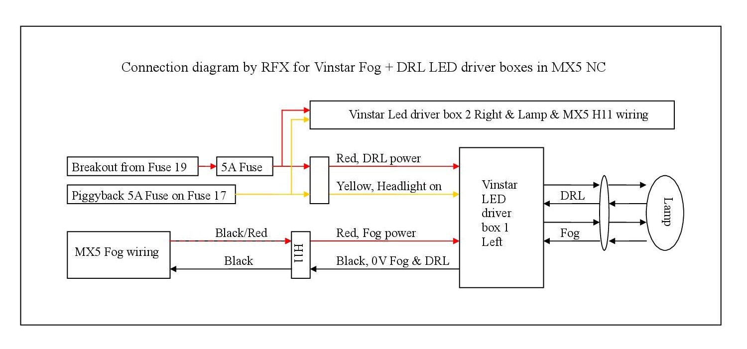
Here is the connection diagram of how I’ve installed it, for completeness sake

I’ve yet to figure out how to turn OFF the DRL when the Fog is on headlights off and the ignition is on, I guess a pair of diodes will do for the switching logic, but where to pick up the Fog On signal?

If the expanding fasteners don’t want to fit their holes to secure the splash guards, let them warm up in a mug of hot water for a few minutes. Then hold the one to be inserted closed down unexpanded for a minute while it cools, and it will be a lot more willing for each of its little fingers to find the hole. I discovered a couple were missing, hence the link.

5 Likes

This is why I’ll never tackle anything electrical…scares the bejesus out of me !!

2 Likes

Those solder/heatshrink connectors sound brilliant, especially for someone totally lacking in talent with a soldering iron like me.
Must get some :slight_smile:

1 Like

So just to clarify how you wired them…

DRL’s come on for daytime driving then go off when the headlights are switched on?

Do the fogs work as normal with headlights on, no DRL’s?

I get what you say about fogs only but the DRL’s come on too, does this happen if you wire as per instructions in the pack from Mx5parts?

Just me being inquisitive, it looks great and many thanks for the ‘how to’ I’m still pondering over buying these for my sport, shall bookmark this if happen to buy them.:+1:

1 Like

Yes, it all works as required. And yes. And yes.

DRLs are On with Ignition On, but go Off when Headlights are On.

Fogs work exactly as before, on the lighting stalk, no change except the LED driver box in the way.
The DRL lead does not need to be connected for the Fog to work.
The Fog lead needs to be connected for the DRLs to work, but only because the fog lead provides the 0V line to ground.

The LED driver box has two input leads and a single four-core output going to combined DRL and Fog lamp. Ignore the picture on the LED driver box, that is completely wrong and is not relevant to this box.
The circuit diagram now in the first post showed what I have installed, only one driver and its lamp connectivity is detailed, the other is the same, only the red and yellow lead goes to both assemblies.

1 Like

Very wise. My excuse is I’ve been doing it since I could barely walk.

Long before Lego, before 13A sockets, before Health and Safety, every UK house had a forest of adaptors, 15A, 5A, 2A, 1A, sticking out of the single 15A socket. These adaptors were always falling to pieces, and putting them together again was my substitute for Lego. It was also how I got my first and only mains belt.

3 Likes

Thanks for the explanation :+1:

Remember my in-laws house, old two up two down terrace, they had adaptors in every socket. I think only one single socket in each room so you can imagine the extension off an extension, he used to have aquariums. He also had sheds in the backyard which also required power, cables everywhere.:grin:
I give him his due he did everything himself, never came to any harm.:smile:

3 Likes

That was normal, the 15A spur routed from its own wire fuse in the fusebox, usually VIR (Vulcanised Rubber Insulation) or very early was rubber with cloth protection inside a lead sheath!

When I bought this (built in 1927) house in 1971 the 13A sockets and ring main had already been “converted” (1960s) by retaining the previously “updated” (1940s) 7/029 VIR T&E spurs and linking the rooms with early (left-overs?) polythene 7/029. Several of the light switches still had three or four cores covered by rubberised cloth with overall lead sheath, and even though all switches were off one wall ran warm!

The meter was going round with nothing plugged in and nothing switched on. Pulling each fuse slowed the meter a bit, and it was only stationary when all fuses were out. The old VIR insulation was soft like cheese, I could peel it off with my fingers. In places the “new” polythene had stretched thin because of being bent too tightly. It was a death-trap waiting for the unwary. So this house had a complete re-wire in 1971 with the latest and best, in the week before we moved in.

A few years back I borrowed a Megger again and the insulation was still good, and so we just changed the fuse board that was fitted in 1971 for a modern one with MCBs and several RCDs, and went through all the sockets and switches looking for bad connections. The Sparky went away happy.

1 Like

Just about to tackle this project… your post will be very helpful… I’m sure I’ll be referring to it again at the weekend


What are these wires for … ??

They live in the little black plug shells supplied in the kit, and those kit shells will plug into the two-pin Mazda H11 socket instead of the original Fog lamps .
The rubber bits keep water out, so make sure they are fully seated in the kit shell after clicking the contact pins in place so they can’t be pushed out. This might happen when plugging the new connector into the original socket for the H11 if these pins are not secure.

IMPORTANT.
When plugged together, the Black kit wire must match up to the Black H11 wire for 0V, and the Red kit wire matches up to the Black/Red H11 wire for Fog 12V.

See my wiring diagram at the end of the first post, it shows the wire colours and the H11 socket.

Always double check things. If you have a voltmeter this can be a great help and reassurance.

Thank you so much for your help … I’m going to change them at the weekend… just ordered the breakout fuse too