The ones I have are separate halo rings, screwed onto the projector lamps, with separate wiring. However, don’t think you can buy the individual parts!  one Halo on mine started to show less light than the other so bought another set. I now have ‘spares’
Barrie
Great. Thanks for the bulb link. I’d assumed these needed different bulb holders for the ‘extra’ feed but apparently not. I think I’ll go with those instead of separate DRLs.
John
If you do get some, please report back.
They sound like a great product 
I’m very envious of folk who can solder neatly.
Last time I tried to splice, I looked up and followed the YouTube videos on how to make a perfect splice and still ended up with a blobby mess… 
1 Like
The switchbacks plug into your existing bulb holders and then push into the OEM holes in the back of the headlights. They are a bit like a grommet style, once in position properly, they form a good seal. The ballasts need fixing to metal bodywork ideally as they generate a bit of heat. All can be done neatly behind the wheel arch liners 
Barrie
2 Likes
Yes I’m not good with solder, function over form for me! not got anything to connect at the moment but might get some anyway!
Barrie
1 Like
My order is placed, Barrie. I spotted the resistors and guessed they may warm up. I’ll let you know how it goes.
Thank you.
John
2 Likes
Hi Barrie,
That’s great, really appreciate your help, thank you.
One question still remains though. The fused red from the DRL’s (marked no 1 on my photo). Where does that go?
 hmmmm, I must confess, I have no idea? It’s a couple of years since I fitted them and have no recollection of that fused wire? Not surprising with me though I’ll msg my mate (bally3) he fitted the same and may have more of an idea! I ‘think’ it’s power for the DRL part of the bulb as the indicators get their power through the OEM bulb holders.
Barrie
My mate sent me this pic
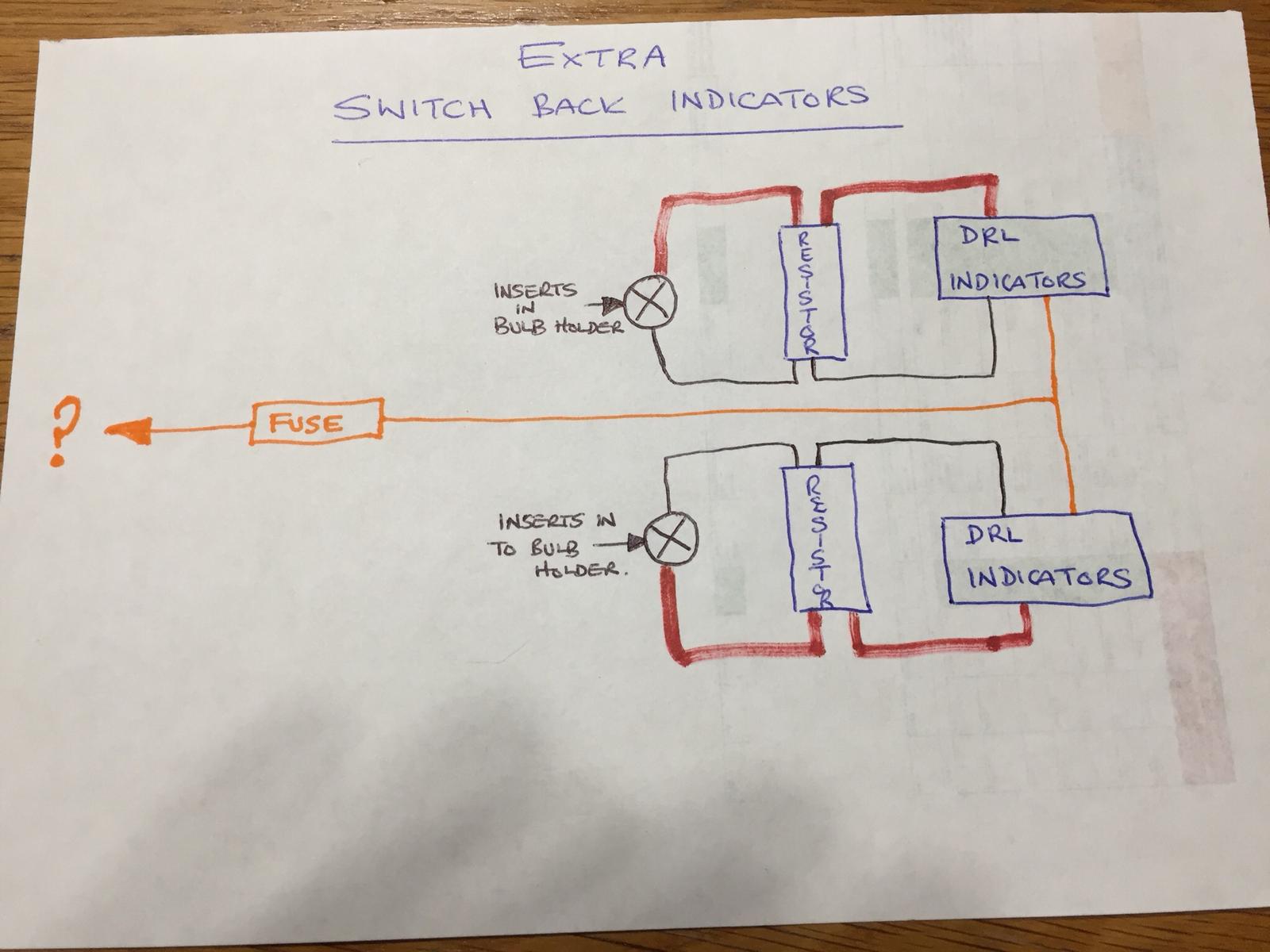
He had the same question mark on his
Well that’s a problem then. 

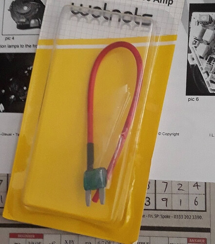
The (?) goes to a 12v ignition controlled fuse (use a fuse doubler) - I “think” from memory I connected it to position 27, but use any ignition controlled one. Check my earlier post/link for photo.

Thank you.
Superstar!
The double-decker add-a-fuse doesn’t fit in those MX5 Parts diagram numbers 26 (Engine) or 27 (Wiper) fuse slots because 35 (IGN KEY1) fuse is too tall. I had to use a different less satisfactory solution.
(I have a Mazda diagram for NC1 which numbers those fuses as 19 (Engine) or 20 (Wiper), and 10 (IGN KEY1) is too tall)
See my pics about 3/4 of the way down my “How to fit the Vinstar DRL-Fog kit from MX5Parts”, specifically using this lead for the switched Ignition feed to the DRLs
I’m sure this is me just me being dum, but, If as is suggested the ‘? (1)’ goes to an ignition controlled fuse, how would the DRL dim when the headlights are on?
Do 1 & 5 not connect to each other?
1 Like
There is a white (or other colour!) wire that connects to the dipped headlight wire probably not shown on the diagram.
Ok, so let me see if I understand…?
The indicators sides of the switch bulbs get their power from the original connections (push into original bulb holders + & -). That just leaves one fused red wire (1); which must be the feed for the DRL side of the switched bulb.
I then have a voltage sensing control unit.
This has a positive and negative (2&3), which go to the battery terminals. Which leaves 3 wires…
The yellow (6) goes to the main beam headlight positive. This dims the DRL when it detects the voltage increases.
We are then left with a positive and negative out (4&5). These must power the DRL, or how else could they dim?
So,… would 5 go to 1 as the positive for the DRL? In which case, where does 4 (negative) go?
My brain hurts!!!
Well rest assured that once you have gone through all of the pain of this they won’t work properly. Or maybe they will at first but not for long. Mine ended up not turning off at all. Complete waste of money on cheap Ching Chong electrics.
Far easier and more reliable to use a changeover relay for the DRLs to switch them off when the headlights are switched on.
JS
1 Like