I have just finished installing a Nextbase dash cam into my soft top MK4 using the hardwire kit.
I took step by step photos along the way. If anyone is interested I can do a tutorial with description and pics.
I have just finished installing a Nextbase dash cam into my soft top MK4 using the hardwire kit.
I took step by step photos along the way. If anyone is interested I can do a tutorial with description and pics.
always interesting to see and would be useful to other mk4 owners ( and others i would hope )
get it done , we like plenty of pics
great idea !!
Please do.
Here is a step through of how I hardwired a Nextbase 322GW series 2 dashcam into my 2018 MX5 ND soft top model.
It is a relatively easy task to do and should take around an hour with minimal tools.
I realise that not everyone is confident in pulling the trim off their car so I have tried to describe the missing detail that I was struggling to find during my search on the internet.
The tools I used were a 10mm spanner for the earth connection bolt, a pair of narrow jaw pliers to remove the fuse, a T30 and a T40 Torx bit fitted to a ¼” socket handle.
These are the Torx bits I used.
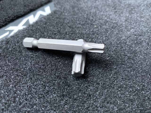
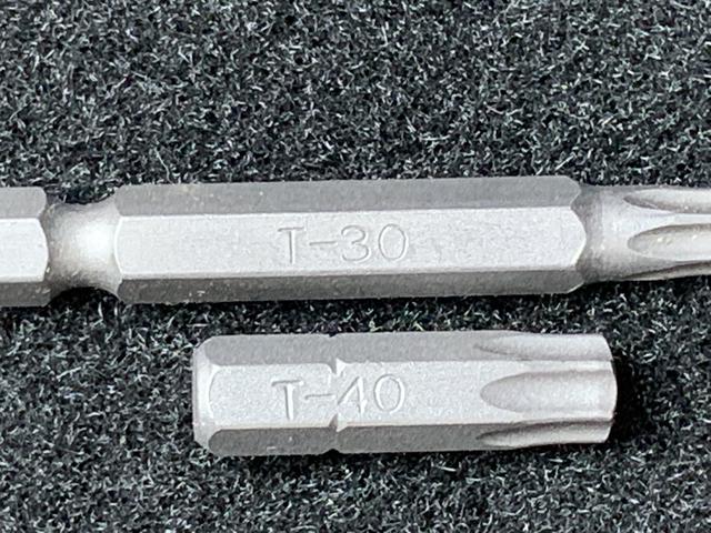
The Torx bits are the only special tools that are needed for this job assuming you have the others in your tool box. You can buy the Torx bits from Halfords and such like.
You will also need a new fuse to replace the one that is to be removed. More on this later. Multi meter (optional).
Unlike cars of old where interior panels were screwed and bolted together, the panels on the MX5 ND are a bit like a Lego kit. Just unclip and push back together again. You do have to be careful of the plastic clips but if you take care then you should have no problems.
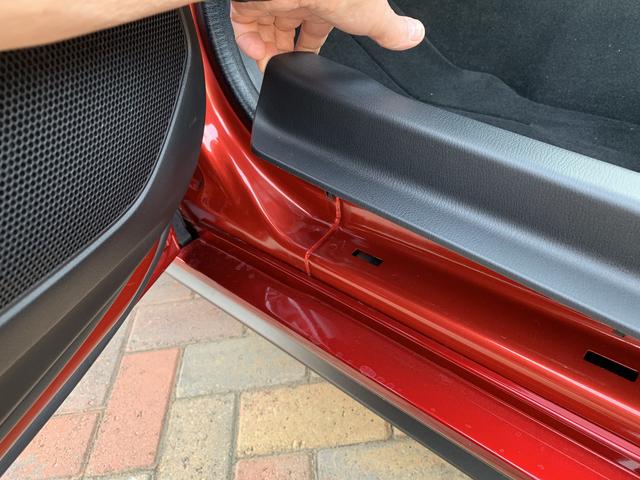
First off is the passenger sill trim, just pull up at one end and remove completely. It is a loose fit so should lift off easily.
Pull the inspection cover off the interior fuse box
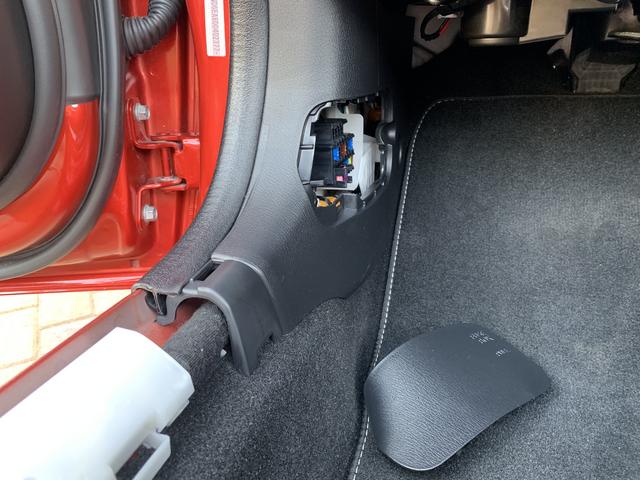
and then lift the edge moulding strip a little bit to reveal two of the fuse box housing brackets.
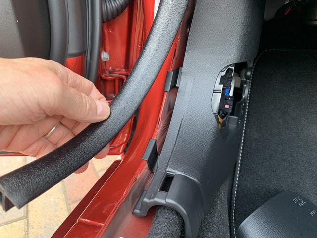
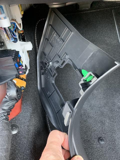
Pull the edge of the fuse box cover towards you. The green clip is one of the clips holding the cover in. Behind that is the bolt that I will use for my earthing point.
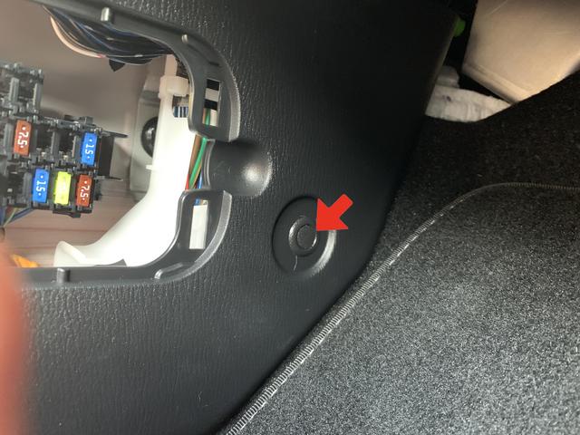
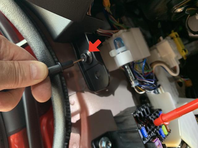
In the passenger footwell you will see the clip securing the fuse box cover (arrowed). To remove this requires a little bit of care. Hold the panel with two hands and give it a sharp pull directly outwards towards the opposite side of the footwell. It is a tight fit.
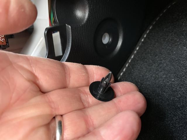
The removed clip is in my hand. Do not try to prise this out with a flat blade as you will mash the panel.
Now the fuse box cover can be removed completely and placed safely out of the way.
On to the wiring.
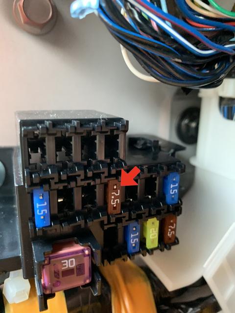
The Nextbase wiring instructions state to use a switched fuse location that does not exceed 20 amps. What this means is you want a fuse that is only live when you switch the ignition on, such as the electric mirrors for example. The fuse that protects the mirrors is a 7.5 amp and as shown in the fuse diagram for a UK spec car, it is position number 8.
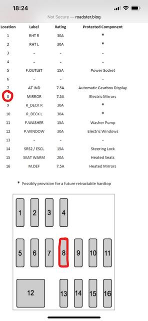
If you count along from the top left you have 4 empty fuse locations and then below that is our fuse location (arrowed). This is the fuse that I am going to remove.
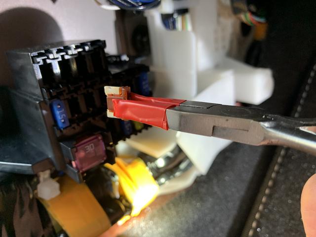
You may have a fuse puller tool located in the main fuse box under the bonnet but my car did not have one so I used a small pair of pliers with some tape wrapped around the jaws to give grip and to protect the 7.5 amp fuse I am going to remove. The fuse is a tight fit but do not wiggle the fuse out as you may damage the fuse contacts in the fuse panel, just pull straight out.
I used a multi meter set to Volts DC to confirm that this is a switched fuse as can be seen with the ignition switched on (19.14 volts). With the ignition off the reading is zero. If you do not have a multi meter then you do not really need to check this. Try adjusting your mirrors electrically with the ignition off!
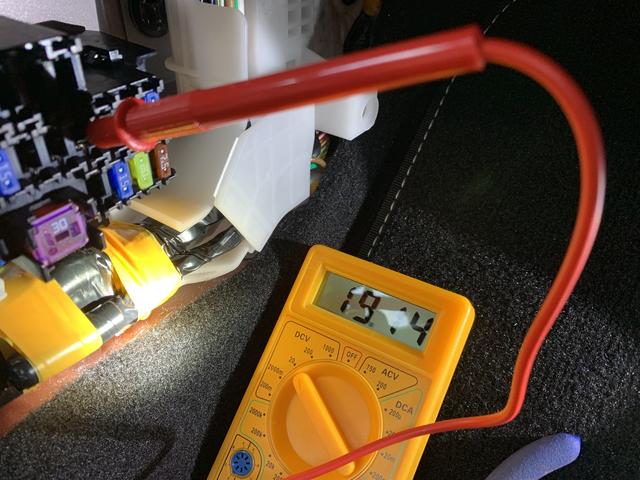
The arrow shows the earth point for the multimeter and proves a good point for my hardwire kit earth connection. This is the same bolt that I pointed out at the beginning of the fuse box cover removal.
Now onto the fuse connector that comes with the hard wire kit. There are two supplied connectors in the kit but we only need the one that has the smaller fuse blades (arrowed). The other connector is surplus to requirements.
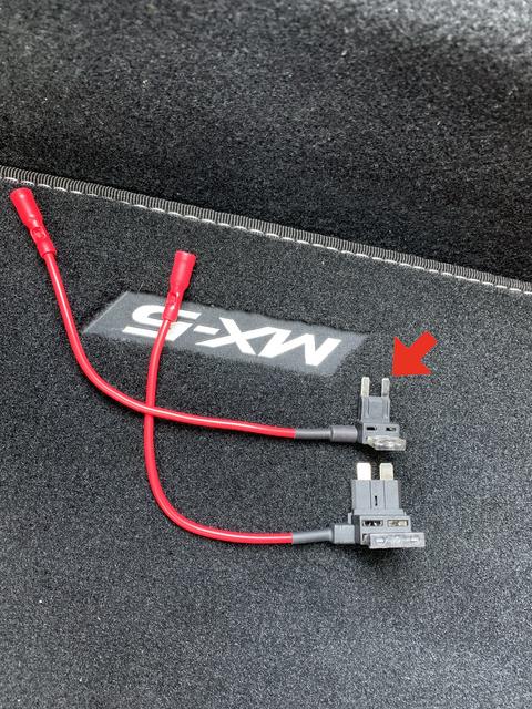
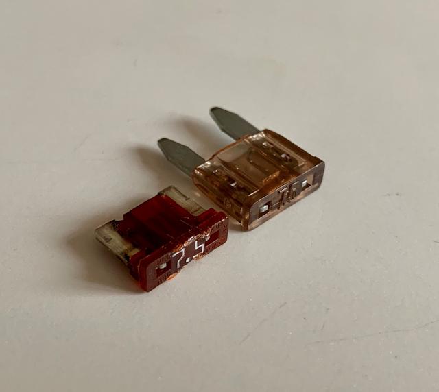
There is a fuse already supplied in the connector and that needs to stay there. Do not remove it. The 7.5 amp fuse removed earlier has to be replaced with a different type. The MX5 has a mini fuse and this needs to be replaced with a fuse of the same rating (7.5 amps in my case) but with longer blades to fit into the new fuse connector.
The original fuse is on the left of the replacement fuse.
I got my new fuse from a local motor factor supplier but I would imagine Halfords or such like would be able to supply the fuse. Just take your fuse connector along to the shop and try one in it.
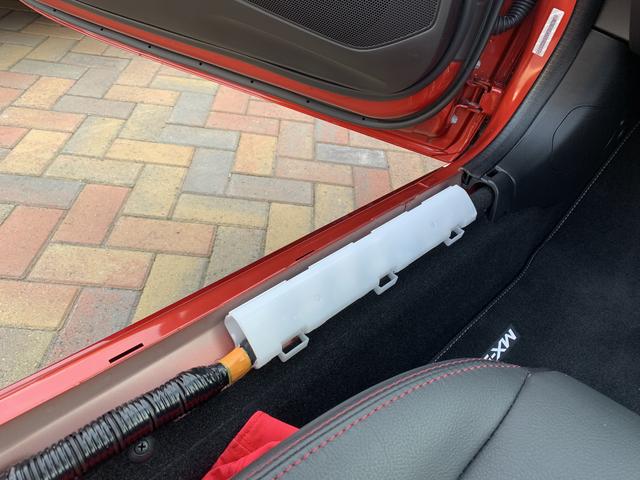
The hardwire kit is around 5 metres in length, way more than enough for my requirement.
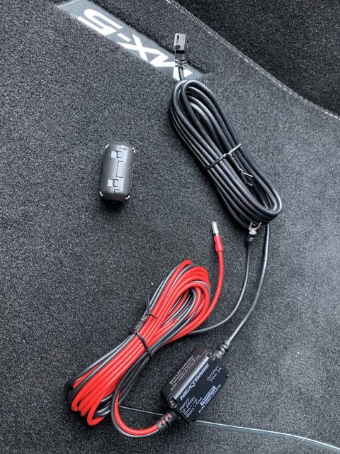
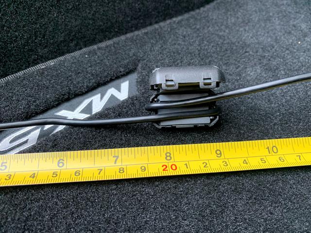
It also comes with a clip on filter to stop electrical interference with FM and Dab radio signals.
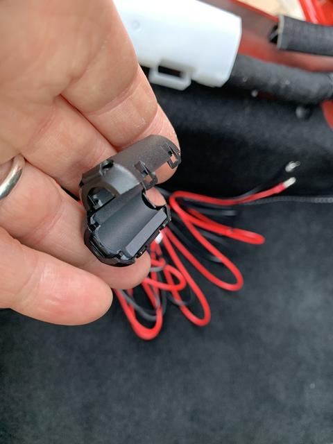
The filter needs to be clipped onto the wire 20cms from the plug connector that fits into the camera magnetic mount. Unclip the filter, place the cable at the required distance and wrap it around the filter. This stops the filter from sliding along the cable. Snap the filter cover shut.
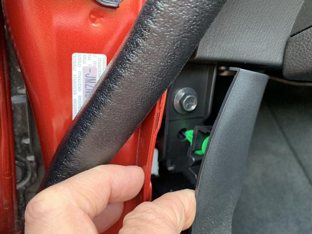
At this point I am going to leave the fuse box for now and move onto routing the cable from beside the rear-view mirror. This is a lot easier that it seems. Slowly lift the top edge of the A pillar cover trim (arrowed).
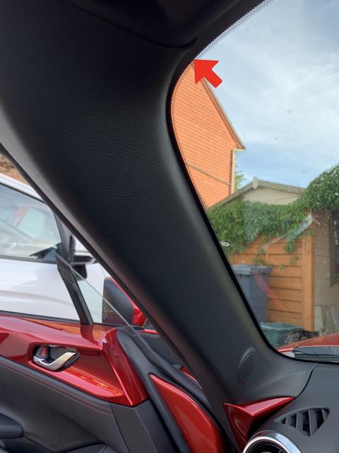
As it comes away along its length pull outwards directly towards the driver’s side A pillar. Remember those plastic clips! We do not want to be pulling sideways against them. There is a clip at the top and another at the bottom of the trim. You can see the square hole where the clip locates.
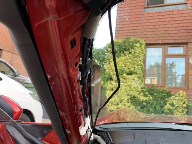
I have a speaker in my A pillar cover trim and I could not work out how to unclip the wired connector to it so I played safe and left it alone. The cover can be laid gently at an angle across the dashboard.
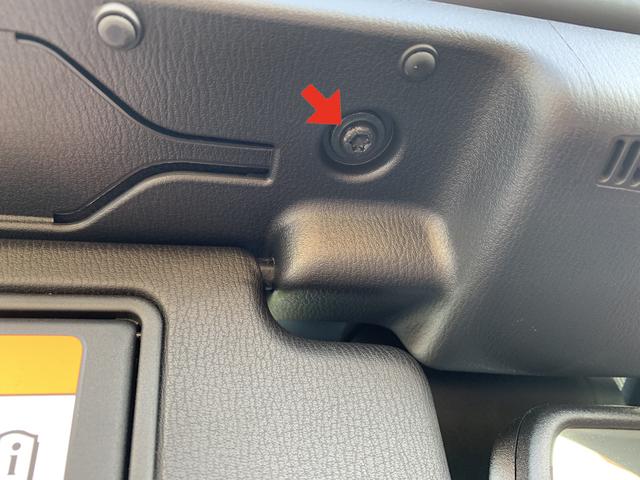
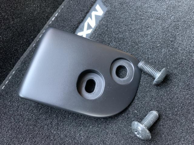
Now for the last piece of trim to be removed. Undo anti clockwise the two T40 Torx bolts (arrowed) to remove the roof catch bracket
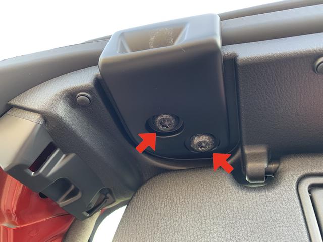
and the single T30 Torx bolt (arrowed) in the overhead trim.
This is where a little leverage is required hence the1/4” socket drive. Make certain that the Torx teeth are always located squarely in the bolt head as it is undone or tightened.
The bracket has elongated holes for correct positioning. More on this later.
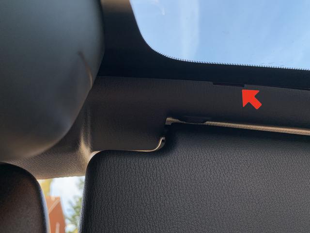
If you twist and look up at the leading edge of the trim behind the sun visor you will see that Mazda have very conveniently provided a small rectangular hole to route our cable from the magnetic camera mount into the trim surround (arrowed).