Thanks for sharing that Bob. It might be something I could use on my hood as it too is beginning to show signs of wear at the joints 
At the Beaulieu Show and Shine, I’d seen quite a few MX-5s with roll-bars (functional) and style-bars (cosmetic). There were a couple of style-bars which I thought looked quite good (I will not be doing track days), so I thought I’d see what was available. It needed to be something that goes with the shape of my seats, which are the one-piece, high-back type. I selected this shape from Moss.
There’s no chrome on my car, so I bought one in black. Easy job to fit – just be careful not to lose any seatbelt washers/spacers down the gaps. Moss also sell a wind deflector, but at £90 for a piece of shaped acrylic (Perspex), I thought I’d try DIY.
I didn’t want to waste too much money if it didn’t work, so after measuring-up, I thought I’d be able to make something from an A3 size sheet of acrylic. I chose 5mm with a grey tint.
After cutting out a number of cardboard templates to get the best fit, I carefully cut the acrylic. I used a jigsaw (fine blade), at very slow speed to reduce the risk of the plastic melting and smoothed the edges with a file and abrasive paper. I then had to figure out how I was going to secure it to the style-bar.
The Moss wind deflector is larger than the aperture and used straps with what appears to be press studs. I thought I might be able to do something with Velcro.
I’d previously used hook and loop ties to neatly secure cables and wires. These are better than simply using a strip of Velcro as they have a slot which allows you to pull it tight around the cables. You can get them with a buckle, but I think this style is neater:
I cut out slots in the acrylic for the ties and this is how it looked:
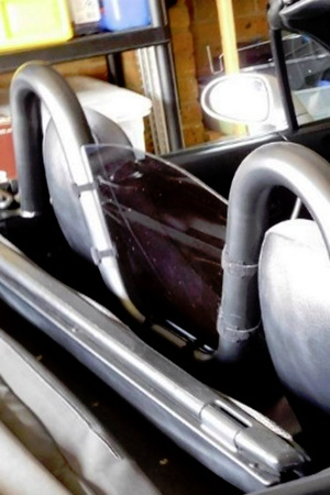
It maintains its position on the style-bar really well and I’ve rarely had to re-tighten the straps.
Finally, a word about the style bar. I am disappointed in the paint – it doesn’t seem to be durable. Despite the blurb on the Moss website, I would describe the original finish as satin black, rather than gloss (which I didn’t mind), but after only a couple of years, the finish has significantly dulled and gone a patchy dark grey. I’ve tried to freshen it up with “back-to-black” products, but any improvement is only temporary. Cutting-back the paint might improve it, or I may have to re-paint it sometime.
Bob
(South Essex)
1 Like
hi Bob, Good luck with your “new” car. I am a newbie, after many years of motorcycling and dabbling in off road motor sport I aquired in 2020 November, a UK 2000 Mk2 1.8 Icon Edition. Sod’s Law the pandemic and the rubbish weather (North East ) has curtailed my progress but it is sorted and ready to go. I have many decades of experience reviving old bikes and the odd Land Rover and trials cars so I have reasonable facilities to tackel anything except of course old age cuts down the enthusiasm a bit.
I shall keep an eye on your progress .
Cheers Steve
Thanks for this thread Bob, it’s really informative and entertaining!
Cheers!
Russ
I decided to replace the Bose Audio/Navigation unit that came with the car with a Double-DIN Alpine unit that I had from another car. I mistakenly thought this would be easy.
It was easy enough to remove the centre console (done it once before for the gaiter), then the centre panel and the finisher around the audio/navigation unit. The problem was – how do I get the unit out? There were slots either side of the unit and I could see some tabs. Out came the many removal tools I’d collected over the years and I had a poke around. It didn’t work – why not? I should point out that, at the time I had only the Mellens manuals that didn’t cover this unit and I could find nothing about it on the internet.
I managed to get a camera around the back of the unit to see if I could figure out how the unit was secured. I could see the tabs, the removal tools were contacting them, but still I couldn’t get the unit out. Much as it pains me to admit this, I got a bit physical with it and eventually got it out by brute force. I can’t explain how, but I remember there was a lot of swearing. Annoyingly, as soon as it was out, I could see how removal should be done. Unfortunately, I broken too many plastic bits so the unit was scrap.
If only I knew then what I later found in one of the Japanese illustrated parts lists. If there’s anyone out there with one of these units, this diagram helps:
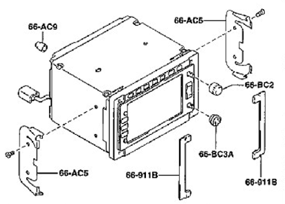
The locking tabs on the side clips (66-AC5 above) are much thicker that the tabs you usually find on audio units. They are visible through slots in the frame, but too strong to be pressed in by the usual removal tools. These slots are a cunning ploy to mislead you – ignore them. Instead you have to insert small screwdrivers or rods into the 4 holes at each corner. This will engage the offset conical guides in the side clips and the tabs will release from the frame. The unit should then pull out – simple when you know how.
The mechanical fit of the Alpine unit was standard DIN stuff.
The Bose system has a separate power amplifiers mounted beneath the heater controls. It appeared that the dash had to come out to access it – too difficult at the time. I didn’t know if the output of my Alpine unit was compatible with the input of these amplifiers, but after a few decades in electronics, I thought I might get away with it - just keep the volume control turned down until I could be sure.
Now I faced the wiring. As to be expected, the connectors between the audio/navigation unit and the power amplifier appeared to be non-standard and, because it was a JDM car, neither the Mellens or Haynes wiring diagrams I had were of any use. So, back to Googling and I found what I needed.
I couldn’t access the power amplifier to get at the connectors (this needed the dash out) so I decided to dismantle the audio/navigation unit, remove the connector and make my own interface cable for the Alpine unit. It turned out to be a bit of a bird’s nest of wires, but it worked – and no smoke.
I went from this
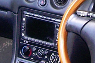
To this
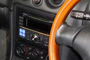
I now had all the radio channels I wanted and a USB port for my prog-rock MP3s. As it turns out, I rarely use it. Hey-Ho.
Bob
(South Essex)
4 Likes
I’ve got wood …
A few years ago I had the pleasure of renting for the day a Morgan Plus 4 from the factory in Malvern. My wife has always liked these cars, so this was part of her birthday present – weekend in Malvern, tour of the factory and a day of wind-in-the-hair motoring. Now I think about it, this was probably what started my idea for a MX-5 as a retirement project. Anyway, the Morgan had a wood-rim steering wheel which I thought was fabulous. So when I first saw pictures of the Roadster, and saw the Nardi wood-rim steering wheel, I just couldn’t resist.
Of course this meant I also had to have a matching wood handbrake grip and a Nardi gearknob to go with it. I soon discovered that, new or used, a Nardi knob for a NB is about as rare as hen’s teeth. Eventually, though one came up for auction on Ebay. I was out-bid.
Undeterred, I found a handbrake grip on Ebay at a buy-it-now price. A bit tatty but otherwise sound, so I bought it. I got to work with sandpaper, woodstain and varnish and it restored nicely. The next part was a bit more difficult. How do I get the original grip off and secure the wood one? Forum answers were simple - slight rotations to break the adhesive seal and pull-off. Mine, of course had to be very well stuck on and a bu$$er to get off. Getting the wood grip on was easier, but I needed something to secure it in place. I used a latex-type adhesive (similar to Copydex) so I could get it off again if necessary.
Now for the knob. There are a few wooden ones out there, including a couple from Nardi. One (Evolution) is like the wood knob for the NA, the other (Prestige) is nothing like the one originally for the NB MX-5. I needed to find an alternative.
I first tried Etsy and then other internet places to see if there was anyone making knobs, and I came across:
He turns both wood and metal, creating threaded metal inserst for the knobs he designs and makes. I sent him dimensioned drawings of the standard MX-5 knob and a picture of the Nardi one. He made this for me:
I was really pleased with my new knob but, strangely after a few weeks it didn’t feel comfortable in the palm of my hand. I decided I needed a new knob - one that was longer and a little bit fatter.
By this time, the second part of my plan for retirement was in place – woodturning. I’d bought a lathe, some accessories and tools, so I thought I’d have a go at making my own knob. As so many times before, I went Googling for ideas and came across a US wood turner making knobs of various designs for an internet retailer.
Inspired, I bought a few M10 fine thread nuts from Ebay, some mahogany/sapele turning blanks and epoxy adhesive. I then set about making a knob, first practicing with some offcuts of wood that I already had. After a few of trial runs, I had a knob the size and shape I wanted.
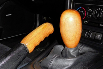
I now have lots of knobs of various sizes and shapes.
Bob
(South Essex)
5 Likes
Frightening how lockdown is affecting us all. Knob pictures flying around everywhere.

Ooo matron ![]()
2 Likes
At this point, I decided to join the MX-5 Owners’ Club. I’d had the Roadster for over a year and, having continued to lurk on this forum, I had read about the benefits and the social activities. What finally persuaded me was the realisation that the first year membership fee would be offset by attending the 2019 event at Gaydon and entry to the museum. My location put me into the North Thames group.
My first North Thames event was an archery experience hosted by a local club, followed by a pub lunch . There’s a postscript to this - I now have another retirement activity, albeit one that has been suspended due to COVID-19.
A day out at Brands Hatch followed. This was an invitation from another group, with some getting the opportunity to parade on the track.
We missed the Spring Rally record attempt, but made it to the National Rally at Gaydon. This was incredible – hats-off to the organisers. We made a weekend of it, staying in Royal Leamington Spa for a couple of nights. This meant we could attend the open-air screening of the Italian Job. We were parked directly in front of the screen, and the weather gods smiled down on us that evening. There was some audience participation (honking of horns during the “traffic jam”), but I was just a little embarrassed (my wife more so) when it seemed I was the only one to sing along with Matt Monroe and start to shout “You’re only supposed to blow the ……”.

A couple more North Thames events followed that year, including karting at the indoor track near me (I didn’t realise I was so competitive), but then 2020 arrived and everything changed.
I was already on my rundown-to-retirement, which meant having to work only 3 days each week. Lockdown put paid to our plans for outings in the Roadster and pub lunches, so I had to find something else to do. No decorating needed (already been done) and, apart from cutting the grass, the garden was looking after itself. Time to do some serious work on the Roadster.
3 Likes
When I bought the Roadster, it had a conventional lead-acid battery in the boot. It wasn’t until later, after reading many forum posts on the subject I discovered what type should be there. I also learnt about the importance of vent tubes. These were not fitted to the battery in my car. Not only that, the replacement battery was too tall and someone had compensated for it by bending the retaining bracket and discarding the plastic tray.
One day, while browsing in Halfords, I spotted a number of vent elbow tubes scattered on the floor under a shelf with the batteries. I picked up a couple, took them to the customer service desk and asked if they had any for sale. The answer was no, but I could have the ones I had in my hand as they’d only throw them in the bin.
When I went to remove the battery from the car, I found the rest of the vent tubing under it and the exit valve still in place. All I had to do was connect this to the battery using the items from Halfords. I did, however notice some corrosion down there – not much but I had to be sorted out. It looked like the battery was fairly old, so I thought I’d refurbish the battery compartment and treat the car to a new Panasonic battery.
I found a source of a used battery tray, but I had to wait a few weeks until MX5Parts received new stock of the Panasonic battery, which happened to coincide with one of their discount periods. I’d read about potential problems with these batteries when a car is not used often, so I bought an isolator to go with it.
I used some old Kurust to treat the corrosion and hand-painted primer and a black top coat. The retaining clamp bent back into shape quite easily. Overall a very straightforward job.
About this time I also fitted parking sensors. Not absolutely necessary, but it makes reversing a little easier and is a bit of future-proofing against any decreasing ability on my part to fully twist around in the seat.
The most difficult part of this job is deciding the optimal location of the sensors on the bumper. It’s not a NB, but this image may help.
Wiring is fairly easy - just break into the reversing lamp for power.
2 Likes
A quickie for anyone out there with an early NB who has problems when refuelling. This is where the pump nozzle repeatedly shuts off flow. I had the same problem and came across this service bulletin:
The workshop manual includes an item on inspecting the valve. Sure enough, the original was a single flap which was sticking. I could only obtain the new part from my local Mazda dealer. The replacement valve solved the problem.
The work involves exposing fuel and explosive vapours in the tank, so I don’t feel comfortable explaining here how I changed the valve.
WARNING - DO NOT ATTEMPT THIS JOB UNLESS YOU KNOW THE CORRECT PROCEDURES AND PRECAUTIONS WHEN WORKING WITH FUEL SYSTEMS, AND YOU ARE COMPETENT TO DO THE WORK.
1 Like
The Roadster failed its MOT test in 2019 due to one of the steering gaiters being split. These were replaced by the garage. Months later I noticed that one of the rubber boots on a tie rod end had a very small split in it, so I decided to replace both of them before the next MOT. I chose these as replacements:
Febi Bilstein Tie Rod End 42458
Internet prices vary so you’ll have to find your own seller. I selected these as they appeared to be nigh-on identical to the originals, which meant I might get away with not having to get the tracking re-done immediately – see below.
I’d done this job on another car many years ago using a hammer to split the joints. The joints on the Roadster appeared to be the originals, so expecting a difficult time, I decided to buy a joint splitter.
Draper Expert Ball Joint Separator 28882
Again internet prices vary considerably for this item, so I’ve not suggested a source. There are other types and brands of splitter, but too cheap may mean poor materials – you want to joint to break, not the tool.
There are lots of Youtube videos for this job, covering all the methods of breaking the joint. This excerpt from Wheeler Dealers gives a good explanation.
This one is for the Mazda 323, but uses the splitter
In his video, Ed China notes differences between old and new joints, requiring tracking to be re-done. I went a stage further and, before splitting the joint I put a dab of tippex on the tie rod and made a reference measurement from the centre of the joint (the fixed bowl part, not the moving pin) to a point on the tippex, which I marked with a pen. Once the old joint was off I measured from the centre of the joint to the edge and compared it with the new one. This meant I could compensate for any difference. As it happens, the Febi Bilstein joint matched the old one. So far, I’ve not noticed any problems with steering drift or abnormal tyre wear.
2 Likes
I next turned my attention to dealing with some rust on the boot around the number plate lamps – another common problem. Mine was not too bad, but had been previously worked on, probably using a pot of brush touch-up paint.
The first thing for me to do was to get some paint and lacquer but, due to the post-accident respray I was worried about colour matching. Did they use the OEM colour code? I’d already bought a pack of touch-up paint from MX5Parts which turned out darker that I would have liked. I also found it difficult to use - I presume it’s water-based.
The VIN identified the original paint as 18G which has a number of associated names, including a Ford colour – probably from the period Ford had a stake in Mazda. After more Googling, I took a chance on this one from Paints4U:
I also bought some Bilt Hamber rust converter, which will also appear in a later post:
Removing the lamps was a bit tricky as the old touch-up job had stuck down the rubber seals, but they came off without breaking and I set them aside for cleaning and refurbishing.
Not much to say about the next bit: rub-down rust and old paint; apply rust converter; mask-off; apply primer; rub-down; mask-off; apply paint; rubdown; apply lacquer.
I had the option of buying new lamps, but the engineer in me was convinced I could re-use the old ones. So I cleaned the old housings and lenses, and, as the old rubber seals were shot, I made a template and carefully cut out new ones from a sheet of adhesive backed foam I had in one of my this-may-come-in-useful-one-day boxes.
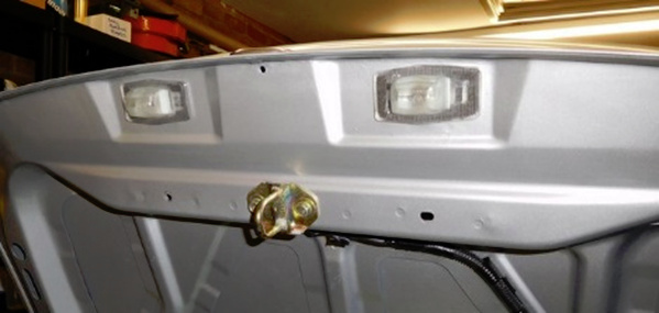
The result was better than I expected – it looked like they’d used the OEM paint code for the respray after all.
3 Likes
Now for the big one – I need to remove the dashboard.
When I got the Roadster, I was aware that the airbag light on the instrument panel didn’t illuminate and extinguish after a few seconds as it should. This was also recorded as an Advisory at an earlier MoT test. Apparently, the test criteria changed a few years ago, so only an indicated fault is a failure.
The previous owner couldn’t recall ever seeing the light and assumed the bulb had gone. In a sense he was correct. When I removed the instrument cluster, I found the bulb had gone – goodness knows where it went. I suspected one of the previous owners had removed the bulb because it flashed fault codes. I connected a light emitting diode (LED) to the diagnostic connector in the engine compartment, anticipating a flashing error code. Instead the LED was permanently illuminated – this indicated a faulty airbag control unit.
Unlike the NA, the control unit for the NB is located in what is probably the most inaccessible part of the car and the whole dashboard has to come out to access it – aarrgh!
I decided to bite-the-bullet, so I bought a used control unit. There are a number of different part numbers for this item but the JDM parts list helped select the one most likely to be in my car. The seller had an image of the car it came from – S registration like mine and no crash damage, so for £10 I took a chance.
Now to find out how to remove the dashboard. I did a lot of research for this one, watching many Youtube videos and reading lots of forum posts. Eventually I came across this – by far the best and most comprehensive video guide I’d come across.
WARNING - DO NOT ATTEMPT ANY WORK INVOLVING AIRBAGS UNLESS YOU KNOW THE CORRECT PROCEDURES AND PRECAUTIONS, AND YOU ARE COMPETENT TO DO THE WORK.
It’s quite a daunting task, but I did it. Actually, I should say we did it as I needed help from my wife for the heavy/awkward bits and she spotted a couple of places where I hadn’t properly released some connections. Although just an incidental viewer of Wheeler Dealers, she said she had picked up a few things from Ed China along the way. 
One big difference from the video – I didn’t remove the steering wheel. Instead I dropped it down onto the seat, which gave me enough room to access the airbag control unit and remove the (now redundant) Bose power amplifier.
I had read that a constantly illuminated airbag warning light could be either a faulty unit or a problem with the connections. There’s a shorting-bar in airbag connectors, which I presume is meant to be protection against inadvertent activation due to stray electrical charge (static electricity) when parts are removed. I read that this shorting bar may also cause the warning light to be permanently on.
Before changing the unit, I decided to test it using a couple of dummy loads (resistors) to simulate the driver’s and passenger’s airbags. The manual gives the resistance required. The airbags had been disconnected to remove the dashboard, so I was able to connect the dummy loads to the airbag control unit. I also reconnected the instrument cluster, which now had a bulb fitted. Low and behold, on powering up the light came on and went off after 6 seconds - just as it should. I removed each dummy load in turn and then both together and the light correctly flashed fault codes. The airbag control unit was working correctly. I presume that by removing the dashboard I had disturbed the connections enough to correct the fault. I spent some time wriggling all the connections just to make sure it was all still OK. As a final test. I repositioned the dashboard so I could temporarily reconnect the airbags. Light comes on, light goes off – result.
While the dashboard was out, I took the opportunity to apply Hydrate 80 to the many areas of bare metal that had surface rust, probably caused by years of humid air condensing on cold metal. This included the steering column and the strengthening bar. I didn’t add any further protective coatings, so it will be interesting to see if (or when) the rust returns.
Finally, after a thorough vacuuming to remove 20 years of dust (including the heater and ventilation items) it was time to put the dashboard back together. As they say, refitting is a reversal of the removal process.
Do I have any tips and observations? Take your time and be methodical. Write down a checklist of what you have loosened, removed or disconnected. This will help ensure nothing is forgotten when you put everything back. I don’t remember any connectors that could be mixed-up, but if in doubt, write on a bit of masking tape and wrap it around the cables to help identify what goes where. Similarly, keep fixings separate (I put them in yoghurt pots which I thought might, one day be useful) and label as necessary
Finally, if I have to do it again, I will first remove both seats. I would have done before, only I couldn’t loosen the bolts at the rear of the seat frames (both sides). I’ll write about this in a later post.
3 Likes
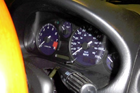
Something’s not quite right with my instrument panel ……
The previous owner warned me that the speedo consistently indicated 5mph higher than the actual speed. Apparently it had always been like this. I decided I’d live with it. There was, however, something bugging me about the dials, which I couldn’t quite identify.
After a few months, having looked at many videos and photos of MX-5s, Miatas and Roadsters, I realised that the dials for the 1.6 and the 1.8 engine variants are different. My Roadster is a 1.6, but the speedo facia appeared to be from a 1.8. On the 1.6 both rpm and speed pointers rest at the 8 o’clock position. On the 1.8 they rest at the 6 o’clock position. A 1.8 facia had been incorrectly fitted to my Roadster by whoever converted it for use in the UK. What had been bugging me was that, at rest, the pointers were not aligned.
I should admit here that I am one of those people who has to straighten pictures on the wall. Once, I fitted a new kitchen cupboard for my daughter and had to make an adjustment because, despite what the spirit level indicated, when I stood back and looked, I could tell it wasn’t quite level. It was only out by 2mm over a 1000mm width.
My obsession got the better of me – I had to change the facia for the speedo.
A quick note – a replacement instrument cluster from a UK car may not work properly with a JDM car. JDM cars were speed-restricted and the speedo stops at 180kph (about 110mph). There are also wiring differences. I did not realise this when I bought one from Ebay, intending to swap the facias over.
I later found this on Ebay and bought one:
Removing and disassembling the instrument cluster is quite straightforward. This video is quite good:
If you are going to take apart the instrument cluster, I advise wearing soft, lint-free gloves to prevent fingerprints on the dials or on the internal surface of the clear plastic window.
After fitting the new facia I had to get the pointer in the right place. I suspected the reason for the original 5 mph offset was due to it not being set properly. Initially, I didn’t fully push down the pointer into the dial and temporarily fitted and reconnected the instrument cluster to the car, but without the clear plastic window. This meant I could set and reset the pointer position during a test drive.
Again, my wife played an important part in this activity. I’d downloaded an app to my phone which used GPS data to give a speed readout. I could have used my TomTom satnav, but the speed display using the phone app was much bigger. We went out to the local dual-carriageway and my wife, armed with pen and paper recorded the GPS speed as I read out the indicated speed. This gave me a series of offsets for repositioning the pointer, which I did while parked in a lay-by. It turned out the initial positioning of the pointer against the end-stop pin was 5mph out. After a couple of test runs and repositioning, my speedo was reading about 1mph above GPS speed from 30mph to 70mph. At this point I pushed the pointer all the way into the dial. Clearly, whoever originally converted the car for the UK didn’t bother to calibrate the speedo. Back home, I assembled everything properly.
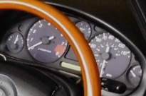
I now have matching pointers and an accurate speedo.
5 Likes
When planning the dashboard removal, I’d intended to remove the seats for better access. Four bolts on each, easily accessible - how hard can it be?
Well, I only managed to get the front bolts out on both seats, the rear bolts were solid. A couple of days of Plusgas didn’t work and there’s no room to get a long breaker bar in there. I gave up trying and did the dashboard job anyway.
Later, while considering changing the differential oil, I’d read that the drain and filler plugs can be difficult to remove – hence the advice to make sure you can remove the filler plug before draining the oil. I tried mine – it wouldn’t budge.
I needed some grunt, so I decided to buy this:
And these:
Powe-e-e-r-r-r-r-r. The differential filler plug came out, as did the seat bolts. Now for the oil change.
A quick note about the seat bolts. The rear ones had corroded, locking both the threads and the mating faces. What concerned me was the white powdery deposit. This may just be corrosion of zinc plating, but the greenish sheen on these bolts reminds me of cadmium plated parts. If this is cadmium “white rust” you must be very careful not to inhale or ingest any of this dust.
2 Likes
Good choice. Six pointers are essential for good grip without damaging the bolt heads.
Time to change the oil in the differential. I’d already had the gearbox oil replaced when the last MoT test was done – difficult to access and my body’s limitations are becoming more and more apparent.
The drain and filler plugs could both now be removed easily so I bought a few bits from Autolink. I figured that I may as well replace the plugs as well as the washers:
Gearbox/Differential Plug Washer 995641800
Differential Filler Plug 995111800
Differential Plug Washer 995621800
I used this oil:
There’s lots of videos and guides on the interwebthingy – just Google: mx5 diff oil change
Another easy job, except for trying to rig up a tube and funnel in the wheel arch. It took ages to fill.
2 Likes
At this point, I’m seeking some wisdom from the collective concerning LSD (mechanical, that is, not financial or chemical).
My JDM Roadster is a 1.6 “Special Package” with a Torsen Limited Slip Differential. I know how the LSD works, but I have had no previous experience driving with one.
Prior to changing the diff oil, the rear offside tyre would regularly “chirp” when turning right out of one particular junction having a slight incline. I originally put this down to the road surface and (at the time) a cheap Chinese-brand tyre. I was wrong about the tyre - it continued after replacing the tyres with Yokohama branded ones. This didn’t really bother me, although to others I may have appeared to be a little energetic in my driving style.
My problem is that since changing the oil, not only am I getting the same chirp at this junction, I’m also getting significant momentary tyre squeal on some roundabouts and bends – even at moderate speed. Is this something experienced by others with LSDs?
I suspect the diff oil was the 20 year old original and had done over 100K miles. Might the fresh oil contribute to a change in cornering characteristics where one side of the diff catches up with the motion of the other side?
2 Likes
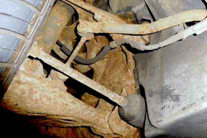
Time to get down and dirty …….
Like so many other NAs and NBs, the suspension components on my Roadster appeared seriously corroded. Everything is structurally sound, but aesthetically, I thought it could be much better.
I’d bought Bilt Hamber rust converter to deal with this and any other significant rust on the Roadster:
I also bought some Corroless chassis paint:
My intention was not to achieve a showroom-type finish, just to improve the look (perhaps also avoiding what appears to be a stock MoT tester’s advisory note) and, hopefully, delay the onset of more corrosion.
Armed with a selection of wire brushes and working one corner at a time, I removed as much of the loose surface rust as I could, but I didn’t bother cutting back to bare, shiny metal – this wasn’t going to be a restoration. This was followed by a liberal coating of Hydrate 80. I left it to do its work and came back to black(ish) suspension components.
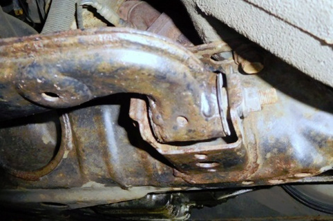
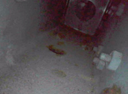
My Roadster is garaged and, wherever possible it’s not used in poor weather - we have another car for everyday use – so I decided on an experiment. I would apply the Corroless paint only to one of the 4 corners, leave it until the spring and then assess whether Hydrate 80, on its own is capable of suppressing further (atmospheric) corrosion. After 6 months, it looks like this:
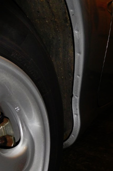
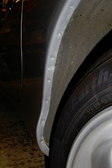
As for the bodywork, everything seems in good condition and there’s no evidence of paint bubbling at the wheel arches, with all original spot welds present:
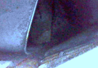
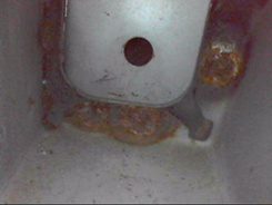
I bought a borescope to inspect the cavities:
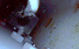
In case anyone’s thinking of getting one of these, here are some examples from mine, showing inside the sills:
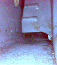
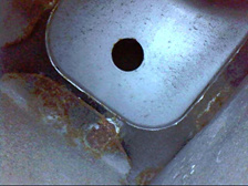
and inside the front chassis rails:
Along with the Hydrate 80 I also bought some Bilt Hamber Dynax S50 for inside the sills and the chassis rails.
This will be a job for the spring/summer. Again, this will be to delay further corrosion rather than eliminate it.
4 Likes