My new precious is a 25th Anniversary

It’s a factory installed “go-faster” sound effect. Zoom-zoom, whether you like it or not. I’m not a fan of it.

Three possible solutions,

  1. delete the whole pipe, costs money and fettling hassle, and suddenly the car is no longer original.
  2. sandwich something stiff and inert (I have some sheet rubber) between tube end and bulkhead, where the arrow points. A bit of unbolting/bolting up hassle, car almost exactly still original.
  3. roll-up some plastic bag and stuff it tightly into the end of the pipe. I can do this when I clear all the leaves and dust out from the scuttle and check both grommets (if any there) are sealed. Easiest, no change to car.

That’s a shame. Do you know where?

I’m very surprised nobody has come up with a 45mn ID cap for the green bit or a fitting with the outlet for the red bit. They would be inexpensive and the easiest way to delete. The other solutions are as you say, expensive for what they are.

The cheapest real method I could come up with to fully delete it is in the pic below for lack of availability of the aforementioned parts, creation motorsports intake pipe, a fitting and some fuel hose. Cost about 55 pounds. I think the official mazda delete kit from mx5 parts is upwards of 100 pounds.

1 Like

In today, 722 miles per year average.


5 Likes

Wow very nice :sunglasses:, lovely colours they chose for the AE. I was so close to going to see some of these, glad I didn’t, I would of been even more out of pocket :+1:.

I put a rubber blanking gasket on the fitting you arrowed on the bulkhead, I’ve since took it off. I couldn’t tell the difference TBH blanked or just left as is.:thinking:

No they wouldn’t say

The guy I spoke to ( I called for a puncture repair about 2 months ago) said they’d miss him as no one else could get close to Joe’s expertise

True, when he did my Niseko, it was transformed from being OK to a delightful dream.
Good new tyres had made it OK, but with his Fast Road setup it became utterly intuitive and went where I pointed, and only there, planted; no wander, no dead spot, and perfectly even tyre wear ever since.

1 Like

Thx for explaining

Today I began the DRL+Fog conversion of the original NC3 Fog lights. Rather than buy a new kit I re-used the one I salvaged from my NC1 Niseko before the Copart guy drove it away onto his multi-car trailer.
Of course while the Mazda fitted fogs are identical, the mounting system is totally different, and doing it this way some fettling is necessary. Some pics follow to show the problem and my solution.
My original 2020 installation on the Niseko is shown here on the forum, and apart from fettling the mountings this went exactly the same way.

Right hand NC3 fog light and plastic housing

The hole it came out of. The metal bracket (for TPMS transceiver) fixed to it at the top left is a right XXX, I ended up springing it out to extract the housing from behind it.

The adjuster slot needs opening out because the Vinstar fog beam has a slightly higher aim.
Before.

And after

The left pivot on the lamp needed its shoulder trimming into a taper, to go into the mounting hole deep enough.

I needed to remove some of the housing to fit the new lamps, the markings show the first cut lines, better not enough than too much, and in the end I needed to file off quite a bit more on the right hand cut, but only a millimetre on the top one.

I used the material from the off-cut to make up a new bit of mounting frame. I have a plastic welding tool, it’s fine on soft plastic things like dustbins and water tanks, but this Mazda plastic was on its upper limit, so the result is strong enough, but a bit untidy. And as my dear old Dad would say, “A blind man would be glad to see it.”

And here it is in the car, with wiring etc tidied away. You can see how much more I needed to trim the ‘right hand cut.’

And the fog-light beam top is at the correct height and drops with distance, the same as the Mazda one did.

See my previous install linked above for tap-in details in the fusebox and a wiring diagram.

1 Like

Part 2 the Left hand DRL, which is subtly different with an extra small problem. They really don’t want us to change the lamp for an after-market unit!

First how it looks as standard

And after removing the lamp which involved all the problems of the RHS plus two cable clips that needed to be released. Fortunately the two clips don’t twist in their slots, and my long-nose mini (5") Visegrips made squeezing the tangs easy and they simply popped out.

Mark up the cut-out based on past experience, the slightly longer piece will be useful.

Cut off the bit bending the wrong way, to become packing filling a small recess, and then the rest is the correct shape, no centre weld needed.

And the result.

Fit the lamp and plug in the two cable clips again, but no new wiring yet.

Final installation with new wiring and switching control all secure and tidy.

Knowing what I needed to do, this one took less than half the time of the other and the welding is neater, but the rough plastic still makes it look bad.

1 Like

Nice work Richard - looking forward to your next project on the 25AE.

Peter

Hi Richard
I have just bought a 25AE too😎

What number is yours ??

I bet it’s a bit cleaner than mine :laughing::laughing::laughing:

Mine was immaculate, gleaming everywhere, but after a two-hour drive home wet most of the way and not enough to wash it, now much less so on the outside.
It could be one of the later ones with its high number 0988 and 64 plate.

1 Like

Now for the Dashcam.
I rescued the camera from the old Niseko, but the hardwired power supply was a bit too fiddly to remove without possibly damaging it, especially considering there is a damaged windscreen right next to all of it. The procedure is much the same as when I fitted it to the NC1 Niseko.

However there are some niggly differences for the NC3, seemingly designed to make it more awkward and significantly less room around the little fuse box.
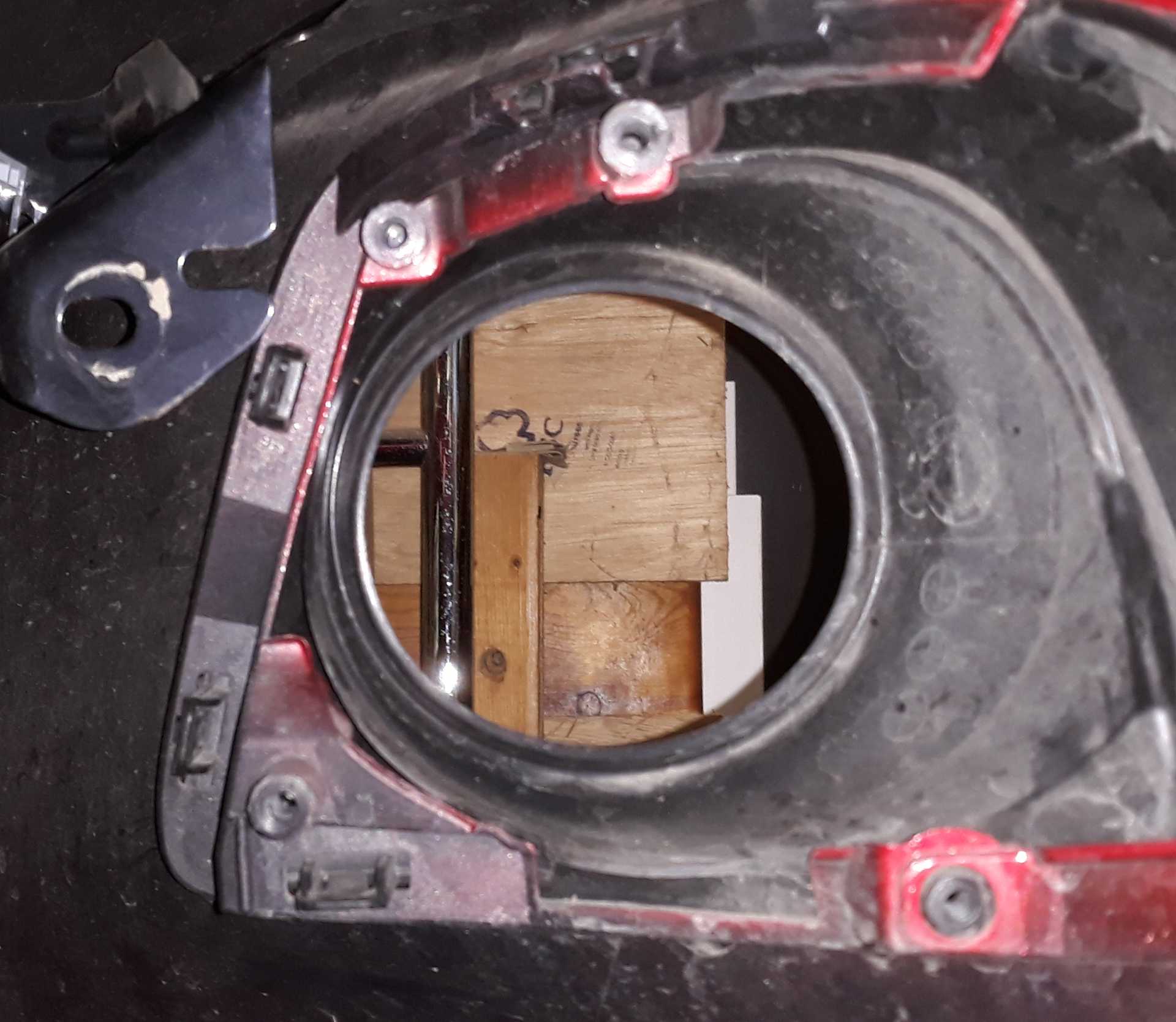
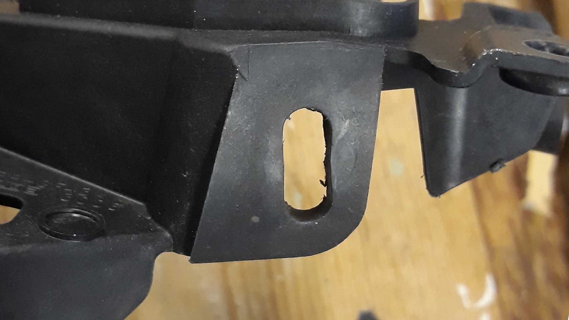
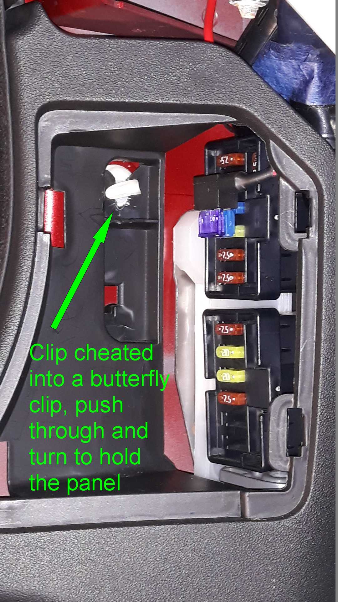
All the panels etc come off easily as before, except the surround of the fusebox where the white clip cannot be removed and the panel has to be slid down off it after having pulled a locating peg clear of the body and lifted clear a bit hooked over the fat loom going to the rear. A pain simply to reach this stage.

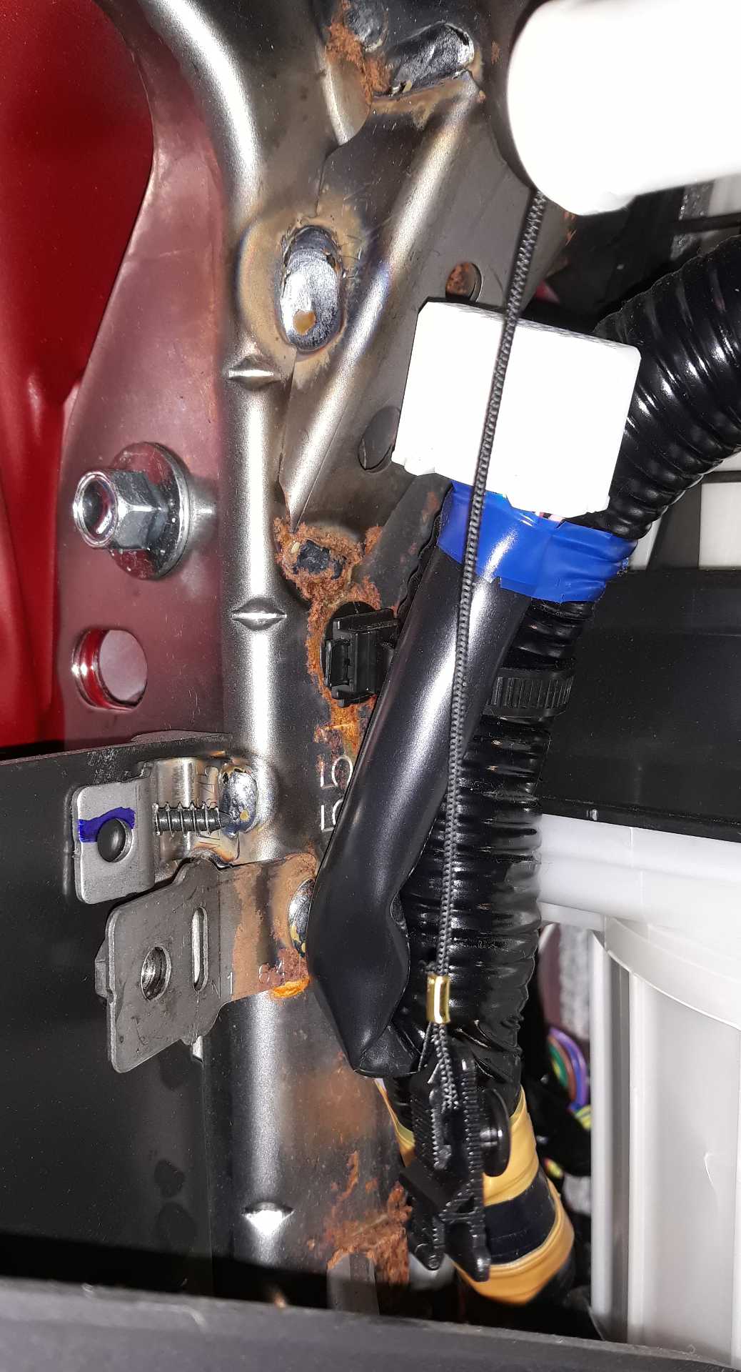
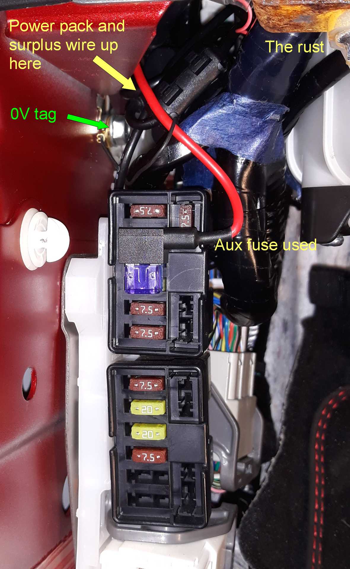
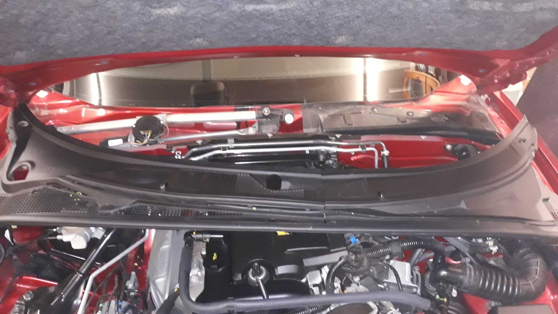
There is a fair bit of surface rust showing for such a low mileage car, definitely a grommet leak although the NC3 scuttle design is quite different from NC1.

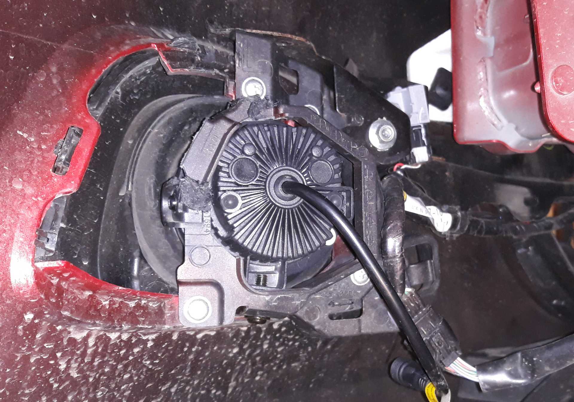
The headliner comes off easily and the interior-light plug comes out with the usual thumbnail squeeze. I planned to put the camera closer to the centre so the passenger sun-visor will not bash it.
However having now done it where marked, it only just misses the mirror and the sticky pad should be just creeping off the shaded bit for another ten mm clearance! The sticky is fake 3M so I expect it will fall off in a couple of months and let me reposition it.

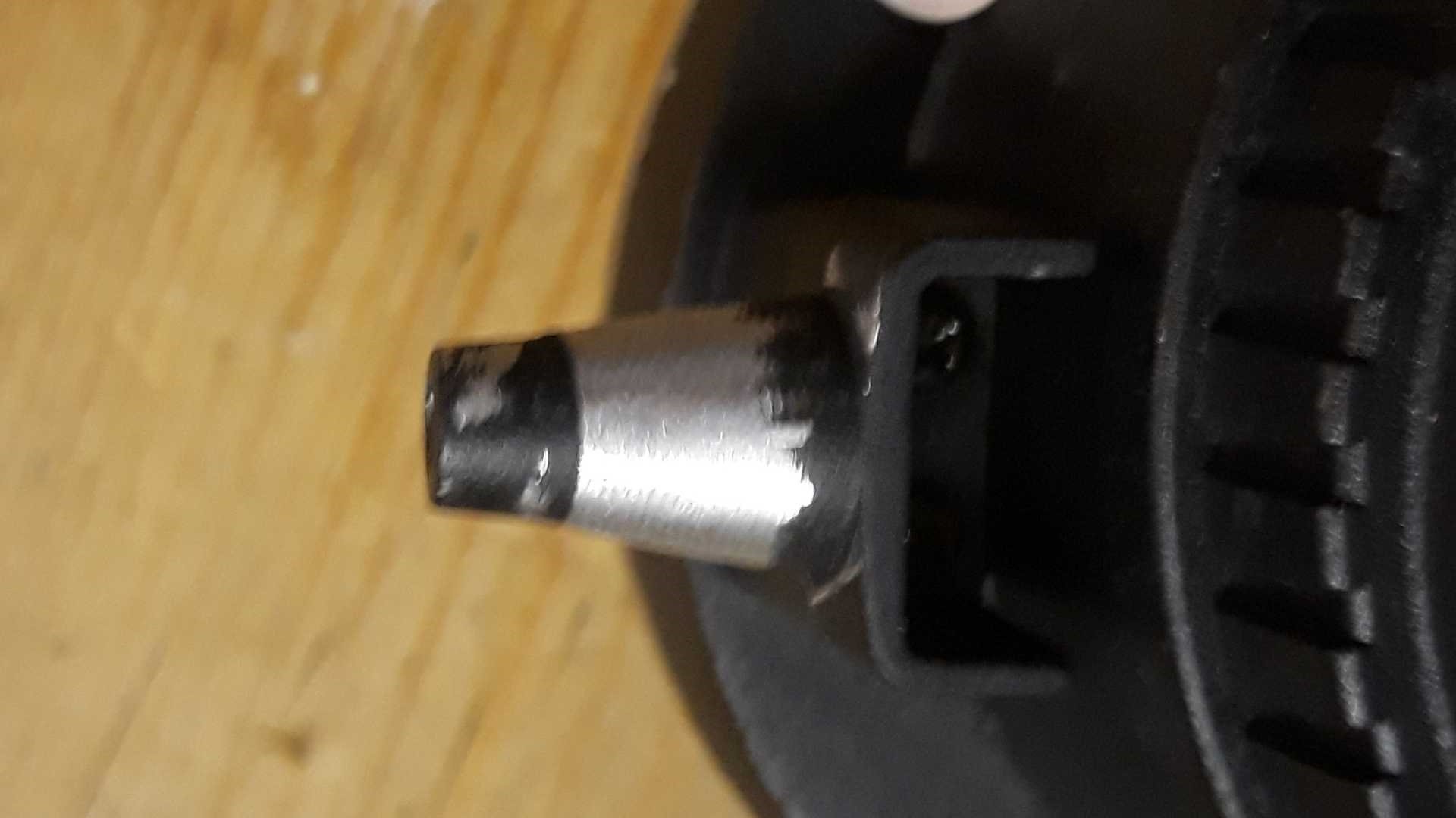
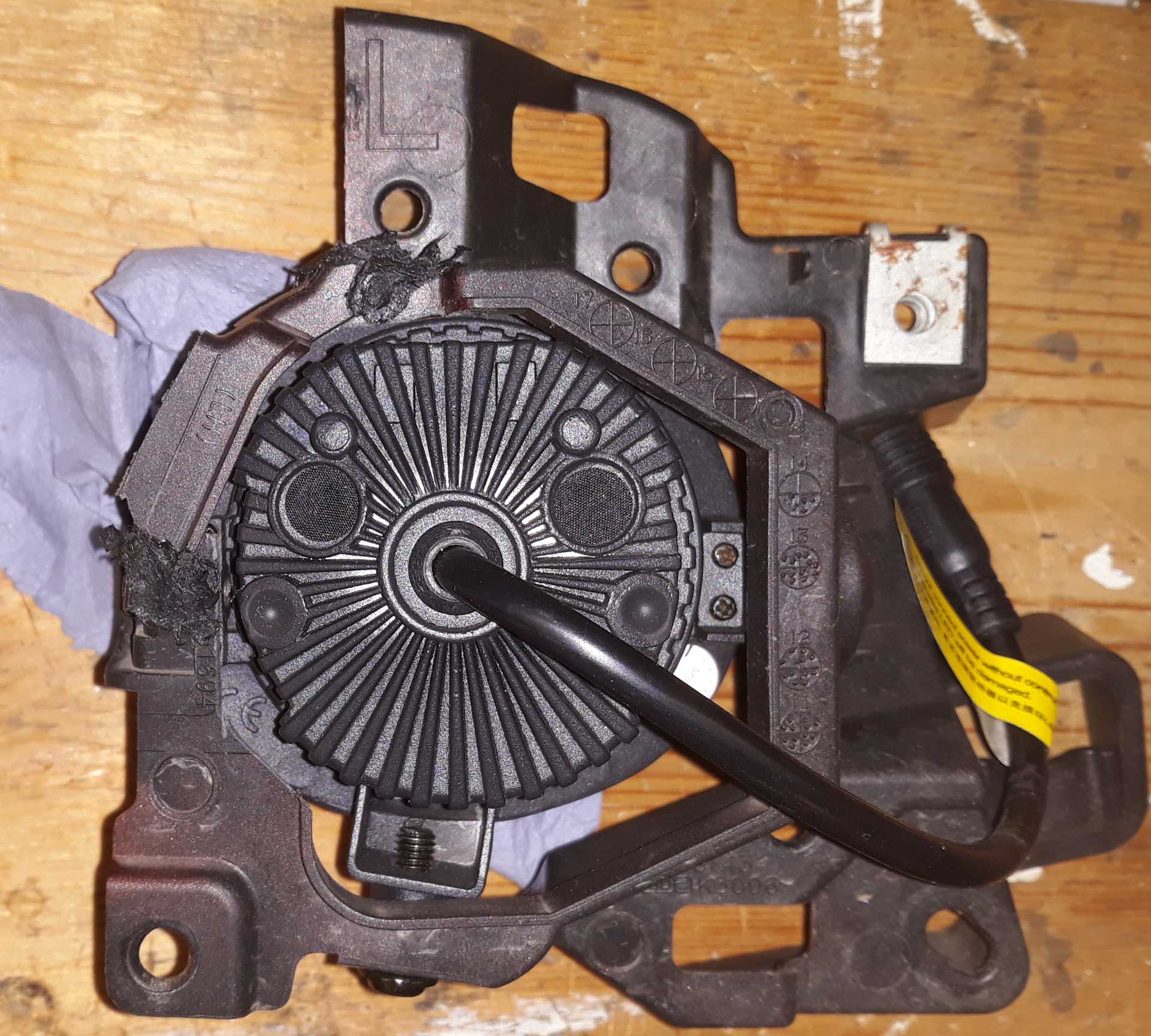
Two of the spring clips stretched their bend so dropped off the heading. I needed to restore their confidence to grip the heading, a gentle squeeze with the Vise-grip and all’s well.

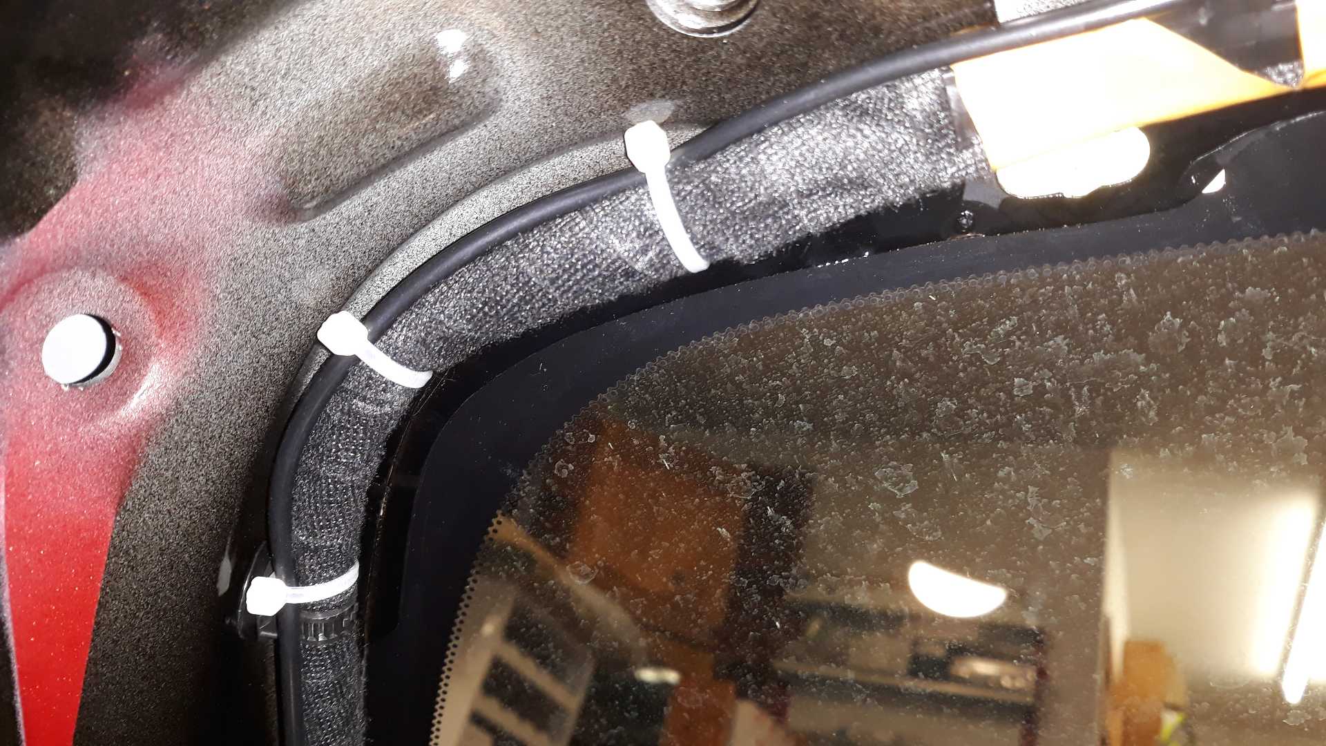
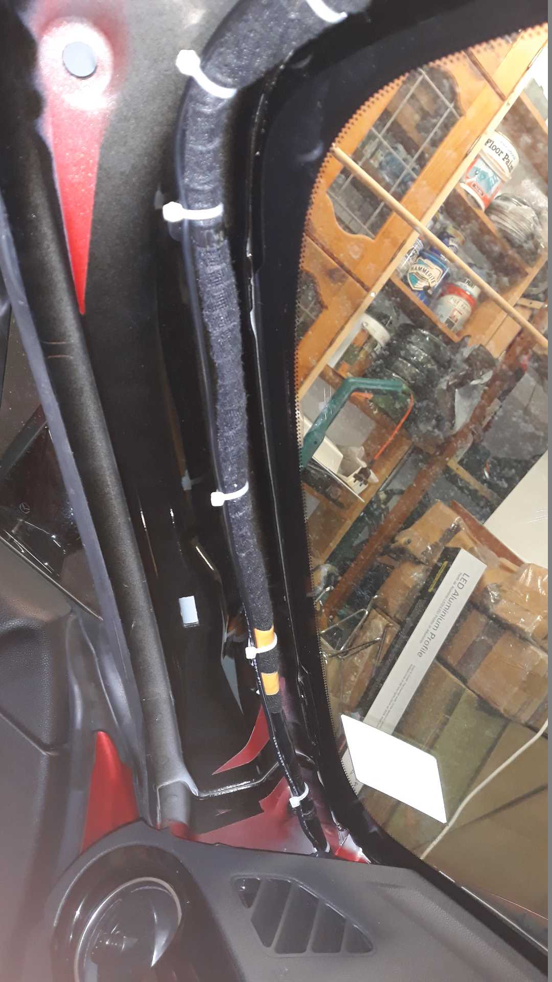
Some cable routing from the freshly fixed mount. Extra ferrites were added at any end of a cable going to a bit of electronics, this to keep radio happy and cameras happy.

All wiring was cable tied to make sure it’s not pinched and doesn’t rattle.

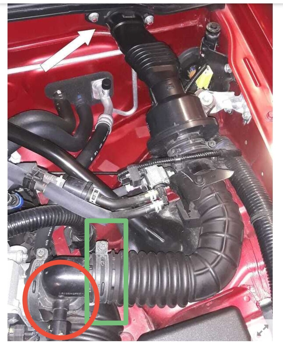
There is so little room for the power block, half the size of the original Nextbase one, that simply stuffing it into the tight space above the fuse box guarantees no rattle or falling out. I used the same earth tag as before, except it is even less accessible, and a 10mm fine-ratchet ring is the only spanner that can get in there. I piggybacked the Aux fuse and not the Acc fuse, because the top of the fuse-block surround-panel might foul the add-on fitting, no difference really, they feed off the same busbar.

The white clip would not come out, but I noticed that my final effort with the trusty Vise-grip had lifted the circle into butterfly wings, and the panel cover would now simply pass over them, and then I could twist it 90 and it would hold the panel again.

All the rest went back as usual, but for one moment of panic. The interior light no longer worked!

Test meter showed volts getting to it, and the bulb was open-circuit. I used the old tywrap trick to extract the bulb and saw the filament is perfect, just a bad connection in an end cap. Another 30mm festoon bulb is on its way, all my old stock is too long. The bulb from the boot fits and works.

1 Like

Scuttle Grommets sealed and scuttle cleaned.

Taking off the scuttle panels was uneventful; no grommet-covers broken, I guess because I levered them up on the rounded end so allowing them to ease out as the cover flexed slightly. It was all surprisingly clean for a nine year old car. I guess the mileage was mainly summer.

The little white T-hooks allow one to stretch the rubber bonnet seal off them, and after some catches were eased forward to allow lifting the front of the pair of scuttle panels it is easy to bring the panels forward just off the windscreen. In this case it was easier to slip the rubber off the hooks than tease them out of the firewall, although two did pop out easily.

Finally while lifting the centre to narrow the ends to clear the back of the bonnet it can be moved to where it is in the picture, washer hoses still attached.

Passenger side grommet was firm, but covered in silt, clearly a flow point; now clean and sealed.

Driver’s side grommet was slightly loose and the washer had shrunk, a thin ty-wrap is an easy way to work some silicone under it before swamping it around the edges as usual.

You can see where I took the ventilation intake shield off how its foam kept the dust out.

The sound enhancing tube will be stuffed with a rolled-up plastic bag. I’ll drill a hole in the tube’s tab through which a cable-tie can anchor the bag in place.

Now stuffed

When the flexi-silicone has gone off (for sure by tomorrow) I’ll reassemble it all.

And a day later, assembled ready for a test drive to make sure SWMBO is happy with the car.

6 Likes

I can see why people would have interpreted this as blueprinting…
In the 70s, some racing rules forbade mods to engines, they had to be standard spec. In those days, manufacturing tolerances were none too precise, so racing teams turned to ‘blueprinting’ to get the most power from their engines.
This involved searching through parts bins for optimum parts that might give a performance gain, eg 4 pistons that weighed the same or 4 conrods that weigh the same
It does sound as though this advertising blurb could be describing a similar process

Define “Blueprinting”. It’s a bit of a nightmare when it comes to competition and everyone sneaking in subtle hidden changes.

Back in the early 1970s I bought a “complete” 2737E 1600 Kent “blueprinted engine” off a friend at work, four boxes of mostly new bits and a +50thou bored-out block. His insurers had refused to let him put it in a notch-back 105E Anglia.

It was supposed to have previously been a Formula Ford 1600 engine. Everything was beautifully matched for balance etc, and lots of bits had been Tufftrided or Nitrided, apparently.

Possible naughty non-blueprint items!! The pushrods were a bit non-standard; the ends were beautifully turned and with none of the usual pressed clamp-marks and rang differently (chrome-moly?) to normal ones, and while the double valve springs were a Ford part these required the valve stem “bucket seals” to be cut back so they were not much better than the O-rings on Mini engines.

However, the ports on the manifolds and the gaskets and the head were not matched, and all different sizes. Using the gaskets as templates I opened out the ports and manifolds by the odd few millimetres here and there to match at their joins and polished up their insides as well.

With a non-standard Lucas distributor (from the dyno operator) instead of the brand-new boxed Ford one, dyno power at the wheels went from 86bhp at 6000rpm to 103 bhp. Being young and stupid, I was delighted and never investigated any further.

I sold that engine into a Caterham fifteen years later.

103 bhp out of a theoretically unmodified, just optimised, Kent 1600 sounds a lot.
What was the claimed output for a bog standard productiin engine?

Congratulations on the new purchase, Richard. The 25th AE is one of my favourites of the mk3. Great write up and documentation of your mods so far.
Enjoy!